
**full parts list below:***amazon electric section: The green wire is used for two things.
35 Boat Bonding System Diagram Wiring Diagram Database

But don’t hesitate to go to a heavier (fatter) wire than the table indicates.
Boat bonding wiring diagram. This is not normally a current carrying conductor. A wiring diagram is a schematic which uses abstract pictorial symbols showing all of the interconnections of components in a very system. So, careful planning and layout is necessary.
The dc wiring diagram below shows how complex dc circuits can quickly become. These colors coded cables are used for bonding in a boat (if insulated). Use this wire size (gauge) to find the correct product.
Before you even begin to wire up your boat you should do all of the following: These are bonding wires i.e. See dc grounding conductor below.
The lower the number, the bigger the cable! This is done because of the galvanism caused by the different metals. Most models also have black white only.
The primary strip should be copper at least 26 gauge in thickness and 1 in width. 1) check all of your bonding contacts, wires, and primary strips. Boat bonding wiring diagram gallery.
Boat switch panel with marine grade rocker switches and rubber seal cap to keep it water tight. It shows the components of the circuit as streamlined forms, and the power and also signal links between the gadgets. The attachment studs should be bronze, (not brass, which is alloyed with copper and zinc), the nuts and flat washers also in bronze, and the connecting wire ends should have tinned terminal lugs.
Even if it’s just a quarter of a volt higher,. It reveals the parts of the circuit as simplified shapes as well as the power. The number in the body of the table at the intersection of this row and column is the wire size (in something known as the american wire gauge);
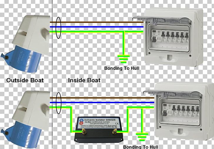
Dc is a two wire system, positive (red) and negative (black or yellow), but there can be a third wire, a green grounding wire or a grounding buss connected to the boat's ground. Bonding systems bonding simply means wiring all the boats underwater metals together. When you make your own wiring diagram use very large sheets of paper for clarity.
Each component ought to be set and linked to different parts in particular manner. On a small boat, sketching circuits in the boat outline helps you locate wires later. Injunction of 2 wires is usually indicated by black dot at the intersection of 2 lines.
Equipment coming off a switchboard or circuit panel should be straightforward to trace. Bonding is hooking all the metal fittings, metal cases of appliances, etc to the common ground, and this can include the hull of the boat. Keeping things simple makes it a lot easy, if you wiring job is complex.
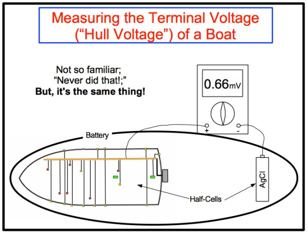
Remember these are all generalities, there are many valid reasons to make exceptions. I'm either not getting +12v through the circuit, and the tank, being aluminum, would itself provide the grounding and the other connector would be the signal wire to the. The same is true of any other combination of two or more dissimilar metals.
On most boats the ground reference is the engine block which is, in turn, connected to the water via the propeller shaft. My sending unit on the tank has 2 connectors, not including the mounting screws to the top of the tank. As stated previous, the lines in a basic 12 volt boat wiring diagram represents wires.
More modern digital nmea networked and multifunction gauges may be all the buzz but the reality is that most boats are still equipped with the same analogue set ups that have been in use for decades. A wiring diagram typically gives details about the loved one setting… It stands for the physical parts of the electrical circuit as geometric shapes, with the actual power and also connection links in between them as thin edges.
Green or green with yellow stripe: By wiring them together, the differing potentials are equalized. I've seen the boat wiring diagram, but that is showing the gauge end.
One is in case you have a ground fault (an accidental short to ground), the other is for what is commonly called bonding. Dc circuits, planning, grounding, bonding, and battery switches. Most boats will have positive and negative busses where area wires come together.
Sometimes, the cables will cross. A wiring diagram is a streamlined standard photographic representation of an electrical circuit. Immerse a bronze propeller and a stainless steel shaft in sea water (an electrolyte), and you’ve just created a battery.
Wiring diagrams include a couple of things: It reveals the elements of the circuit as simplified forms, and also the power and also signal links in between the gadgets. On a bigger project, some planning is nice, so a simple diagram might get used, if only to optimize wire runs, ganging things together, etc.
Symbols that represent the ingredients inside circuit, and lines that represent the connections together. It contains directions and diagrams for different varieties of wiring methods along with other things like lights, home windows, etc. On a simple boat, like an 18' bow rider or similar, i don't use them, just running each wire as i need them.
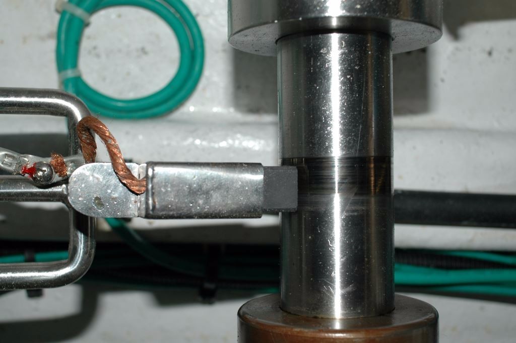
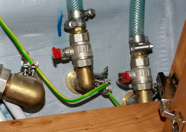
A wiring diagram is a simplified standard photographic representation of an electric circuit. However, it does not imply link between the wires. For those of you who have no idea what the bonding system on your boat looks like, the photo below shows a green wire connected to a sea strainer.
Collection of boat bonding wiring diagram. Boat building standards | basic electricity | wiring your boat inside boat wiring schematics by admin from the thousand images on the web concerning boat wiring schematics, we all choices the top series with ideal quality exclusively for you, and now this photos is actually considered one of graphics selections inside our very best graphics gallery concerning boat. Variety of boat bonding wiring diagram.
That wire is there to attach the strainer to the boat’s bonding system. Determine if you have a bonding buss for the underwater metals, this is a green wire (or a copper strap) that runs through the length of the boat and connects all of the underwater metals. One of them has to do with bonding and grounding, the other anode consumption, and the third with transducers and fairing blocks.

How To Check Your Boat's Bonding System in 2020 Boat

Boat Bonding System Diagram General Wiring Diagram
Marine Bilge Pump Wiring Diagrams Wiring Diagram Schemas
Marine Grounding Systems West Marine

34 Boat Bonding System Diagram Wiring Diagram List
Wiring Diagram 32 Boat Bonding System Diagram

Boat Bonding Wiring Diagram

Boat wiring, Tracker boats, Boat restoration

Boat Bonding Wiring Diagram Free Wiring Diagram
Boat Bonding Wiring Diagram Gallery Wiring Diagram Sample
29 Boat Bonding System Diagram Wiring Database 2020


Boat Bonding Wiring Diagram Free Wiring Diagram

Boat Bonding Wiring Diagram

Getting Grounded the Right Way Diagram, System, Boat

Boat Bonding Wiring Diagram Free Wiring Diagram
Boat Bonding System Diagram General Wiring Diagram
Are My Seacocks Bonded Correctly?
Sailboat Wiring Diagram Ac kaprisnaehwelt

Wiring Diagram Database Bremas Boat Lift Switch Wiring
