
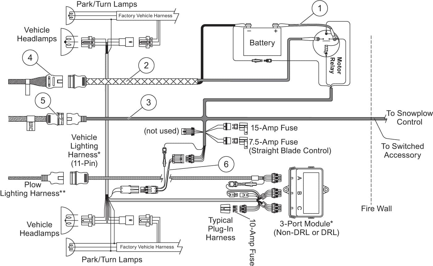
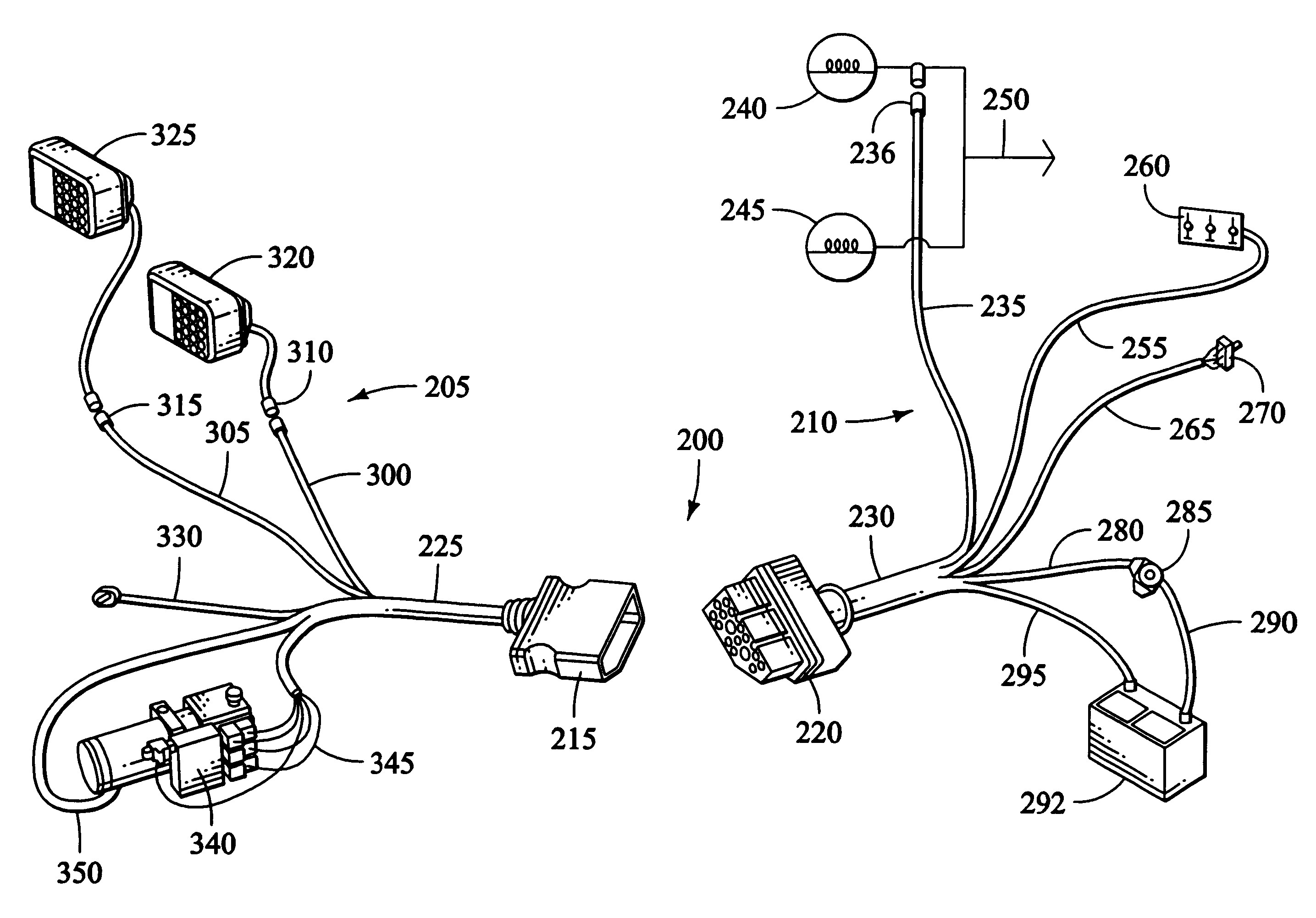
See also ge refrigerator wiring diagram sample. Electrical system wiring schematic (plow side) g10271.
35 Boss Snow Plow Wiring Diagram Wiring Diagram List
Hydraulic manifold wiring diagram figure 4.
Boss plow wiring diagram. Mt n united states formno. If you have further questions, your local boss dealer is the person to. The boss snow plow wiring diagram simple wiring diagram for boss snow plow boss plow wiring diagram v boss v plow wire harness installation boss snow plow wiring harness.
8 27 2004 9 59 47 pm. The cable is 128 in length. With its simple attaching system, the boss can be attached or removed in.
Boss rt3 v plow wiring diagram from www.untpikapps.com. Wiring diagram comes with several easy to follow wiring diagram instructions. Rt3 straight blade manifold g10042 wire color wire function green blade left red blade right white lift orange lower red/black blade right
It consists of instructions and diagrams for different varieties of wiring methods along with other items like lights, windows, and so forth. Each component should be set and connected with different parts in particular way. If not, the structure will not work as it should be.
12 boss plow wiring diagram truck side snow plow trucks snow plow truck. It really is intended to assist all of the common consumer in developing a correct method. Effectively read a cabling diagram, one provides to find out how the components inside the program operate.
Connect the plow side wiring harness to the hydraulic valve manifold as shown in figure 26. Recommended vehicle models refer to the boss snowplow application chart and selection guide. Fisher homesteader plow wiring diagram wiring diagram is a simplified good enough pictorial representation of an electrical circuit it shows the components of the circuit as simplified shapes and the skill and signal links amid the devices.
A wiring diagram is a simplified standard photographic depiction of an electrical circuit. Boss part msc08001 2008 up vehicle side wiring harness 13 pin is used on all boss full sized truck plows. Wiring schematic wiring schematic g10004.
Snowplow assembly procedure 5 figure 4. The boss snowplow has been carefully designed and built for years of carefree performance. Insert the unconnected ends of the plow wiring harness into the back of the coupler through the rubber grommet.
Each part should be set and connected with different parts in particular manner. 6 red black driver side in. Hyd07044 with smarthitch2tm wiring diagram on page 18 of this manual.
Wiring diagram consists of numerous detailed illustrations that display the relationship of various products. For example , if a module will be powered up also it sends out a signal of 50 percent the voltage and the technician would not know this, he would. Where a frame and moldboard fatigue are a common problem on.
If not, the arrangement won’t work as it ought to be. Boss rt3 v plow wiring diagram. For safety the boss includes cross over pressure relief to prevent damage by overstress.
All wires need to be connected. Each component should be placed and linked to different parts in particular manner. It will show you how to use and service the boss, familiarize you with all of its parts, and give you helpful tips on plowing snow.
These directions will be easy to comprehend and apply. We have accumulated lots of photos, with any luck this image serves for you, and also assist you in discovering the solution you are looking for. Boss snow plow wiring diagram thanks for visiting my internet site this post will review concerning boss snow plow wiring diagram.
Otherwise, the structure won’t function as it should be. Vehicles equipped with air bags are designed such that the air bags will be activated in a frontal collision equivalent to hitting a solid barrier (such as a wall) at approximately 14 mph or more, or, To keep your boss plow in top shape, take a few minutes to study this manual.
The plow is mounted on the vehicle. Plows, a boss plow will stand up to severe plowing conditions. Electrical system wiring schematic (truck side) electrical system wiring schematic (truck side) g10272.

Boss Snow Plow Parts Diagram Wiring Diagram

Boss Plow Wiring Schematic Free Wiring Diagram

Boss V Plow Wiring Diagram Free Wiring Diagram
Boss RT1 vblade The largest community for snow plowing

12+ Boss Plow Wiring Diagram Truck Side Truck Diagram
RT3 wing not functioning The largest community for snow
Plow Side 11pin to 13pin The largest community for snow

Boss Plow Side Wiring Harness WIRGREM
19 Images Boss Plow Wiring Diagram Ford

Boss V Plow Wiring Diagram Wiring Diagram
Boss Rt3 V Plow Wiring Diagram SHERRODSTAMPS

Boss Plow Wiring Schematic Free Wiring Diagram

Boss Snow Plow Wiring Diagram Boss Snow Plow Boss Snow
Boss Rt3 V Plow Wiring Diagram


Boss Snow Plow Wiring Diagram Western Plow Unimount

Boss Plow Wiring Schematic Free Wiring Diagram
Boss Plow Wiring Diagram

The Boss Snow Plow Wiring Diagram Gallery Wiring Diagram

The Boss Snow Plow Wiring Diagram Gallery Wiring Diagram