
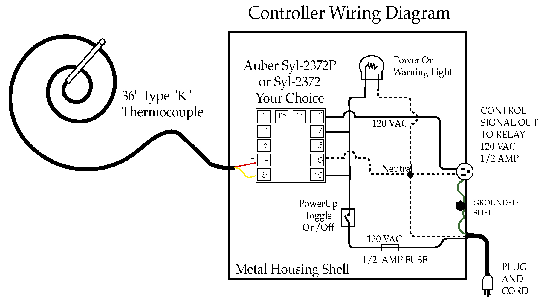
Carel thermostat wiring diagrams standard installation installation with ssc (smart speed control) 12v installation for spillover fan carel 1 2 4 5 7 8 digital thermostat/thermometer 12v positive (+) 12v negative (‐) “c” terminal on controller fuse, 2 amp “t” terminal on controller Alternatively, a second control cycle can be activated with independent set point, diff erential and dedicated outputs.
[DIAGRAM in Pictures Database] Ps2 Slim Schematic Wiring
The tabs at the back will snap into place and lock the controller.
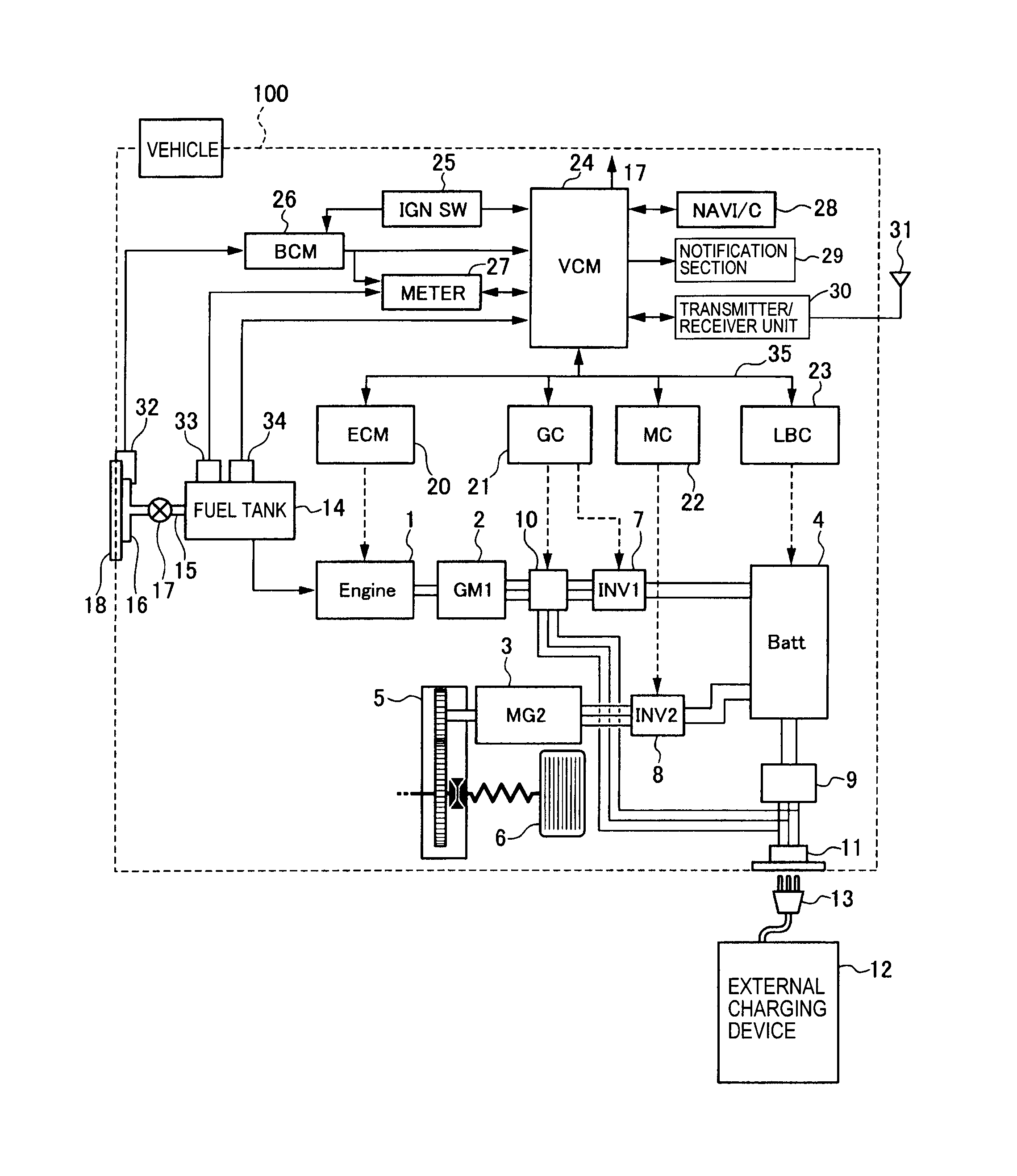
Carel controller wiring diagram. Connect the power cable and digital input cable: Compared to pco sistema, the range is enhanced by a new compact controller, and consequently 1.2.2 fastening to the wall
Carel controller electrical wiring diagram be sure all power sources are turned off before checking the electric wiring or appliances to. The evaporator is a flooded shell and tube design using enhanced surface finned copper tubes. For the 25 to 45kg/h models (compliant with din 19535, uni 8451/8452).
The power supply must be protected by a breaker or a fuse. This is a instructional video on how to program our carel pjez* easy digital controller · the programmed carel skope ir33 electronic controller · copy of this service bulletin including wiring diagrams (prn2997) · replacement controller flex and 3 new controller probes.
Identify the controller / thermometer. Irevxxhxxxx 115/230 v~, 50/60 hz 6 va, 50ma ~ max. Large number of customisation options, thanks to the removable plastic front panel.
Run power wiring in conduit to vgn controller box. Airedale easicool downflow eev control. Control can be set as on/off (proportional) or proportional, integral and derivative (pid).
Power supply model voltage power. The first relay output (refer to internal wiring diagram) of the controller must be a solid state relay (ssr) to tolerate the high number of cycles. Return it in reverse order.
Connect new probes to controller as shown in wiring diagram. Carel description set point differentia neutral zone models msyfch syfch syfch def def. Irevxx0xxxx 12 v ~, 50/60 hz, 12/18 vdc only use selv power supply.
Irevxxexxxx 230 v~, 50/60 hz 3 va, 25ma ~ max. Repeat step for number of fans installed and connect as labeled 1, 2, 3, 4 for corresponding fan. Ssc (smart speed control) wiring diagram:
Polarity is not important 18 gauge wire may be used. Diehard 200 amp battery charger jump starter wiring diagram; Thermostat (digital and mechanical) to compressor's control module,, wiring diagram.
Aguilar obp 3 wiring diagram; The drain water is connected using a section of rubber or plastic hose resistant to 100°c, with a recommended inside diameter of 32 mm or 40 mm. Kenwood kdc 138 wiring harness diagram;
The display will light up, and the driver will be immediately operational if. Merlin ii, mini smart speed control. More space available for wiring;
The evaporator shell is insulated with 19mmsed clo ‐cell foam (max k factor of 0. St 20 60 oc/of oc/of oc/of 16 34 16 34 r/vv minimum set oint maximum set oint operating mode 0 = direct with defrost control (cooling) 1 = direct (coo ing) 2 = reverse (heatin ) Clock for real time defrosts;
Then simply lift the front cover and pull out to remove it. These features ensure that mastercella is the best solution available on the market. A second probe can be connected for diff erential control or freecooling/freeheating, or for compensation based on the outside temperature.
It is constructed in accordance with asme code for a refrigerant side working pressure of 1320kpa and is tested for a maximum water‐side pressure of 1000 kpa. Each fan is provided with (3) 10 meter cables; • 24 vac fan run contact • bms communications • proper incoming power 4.
In this video we look at the wiring process for installing a dixell temperature control that are most commonly found on reach in coolers and freezers on comm. Api electric 16mm wiring diagram; Irevxxlxxxx 12 to 24 v ~, 50/60 hz, 12/30 vdc 3 va, 300 ma ~/ madc max.
Possibility to install a main switch; Irevxxaxxxx 115 v~, 50/60 hz 3 va, 50ma ~ max. Its fl exibility allows for creation of tailor made control solutions according to customer specifi cations.
General connection diagram is a practical example for preparing the unit wiring diagram that fully. Jl 2 250.1 wiring diagram; The ssr on the dcm control is pilot duty, and is used to drive a larger current rated external ssr.
Hitachi wired control for two units. Everbilt sprinkler pump wiring diagram; · 1 large cord grip for retention of new flex.
All wiring by others per local codes • place the controller on the din rail and press it down gently. The figure below shows the dimensions for each size.
For the maximum length, see the technical specifications; Pioneer deh 245 wiring diagram; Cables enter from below or above;
Twist the carel logo to reveal the screw, and use a phillips head screwdriver to remove it. The front cover is secured by a capture screw located underneath the carel logo. Ignition wiring diagram for alliis chlamers ca tractor;

Carel Controller Wiring Diagram

Carel Ir33 Wiring Diagram

Carel Pressure Transducer Wiring Diagram / Innovative Cold
Carel Ir33 Wiring Diagram
Carel Controller Wiring Diagram

Carel Pressure Transducer Wiring Diagram / Innovative Cold
Carel Ir33 Wiring Diagram

Looking for a wiring diagram for Corel IR32C0LBR0 can you help

Ncs Alarm Wiring Diagram HOPESYOUNGADULTCHALLENGE

Ncs Alarm Wiring Diagram HOPESYOUNGADULTCHALLENGE
Chiller Control Wiring Diagram HANISHAARI
CAREL CONTROLLER INSTALL AND SERVICE MANUAL Manualzz
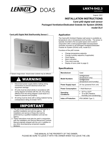
Lennox Wall Sensor DOAS Installation Instructions
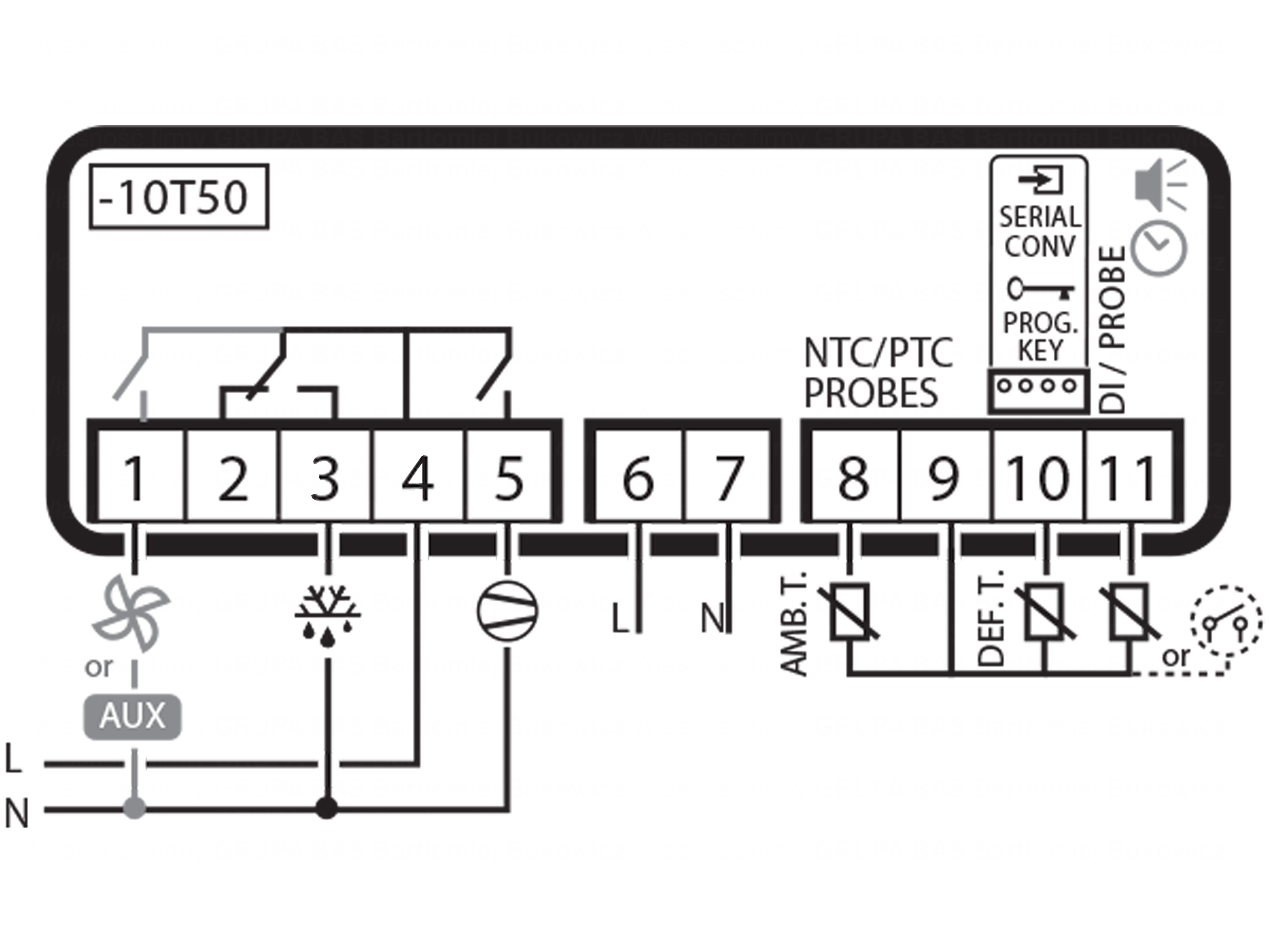
Elektroniczny termostat do chłodni, regulator temperatury

Carel Ir33 Wiring Diagram
Carel Ir33 Wiring Diagram

Carel Ir33 Wiring Diagram
Carel Controller Wiring Diagram

Carel Ir33 Wiring Diagram