
This is the wiring diagram for the hive receiver that will go. For those boilers which have a programmer or timer built in, the only other device required is a room thermostat.
Salus Thermostat Wiring Diagram Top Hive Thermostat Wiring

Existing boiler hot supply 1 central pex® this horizontal assembly must not exceed a height of 4 inches above top of.

Central boiler thermostat wiring diagram. Central heating thermostat wiring diagram collections of ac thermostat wiring diagram download. Gravity hot water controlled by a 6 wire valve not your standard 5 wire valve and a pumped central heating circuit controlled by a thermostat. Boiler wiring diagram diagrams schematics stunning steam with boiler wiring diagram in 2021 boiler thermostat wiring central boiler honeywell y.
We address them in order from most common to least common. Obtaining from point a to aim b. In this hvac training video, i show how to wire the low voltage control wiring for the thermostat, air handler, and boiler for air conditioning and for radia.
Reconnect the red and white wire, tighten down the set screw, and put the control panel back on. If this is the case, you should check with your specific. Where three plans are illustrated there is one for wired, wireless and wireless enabled controls.
Greenstar ri (9kw to 24kw) wiring diagram. Variety of central boiler thermostat wiring diagram. Print the wiring diagram off plus use highlighters to trace the signal.
System diagrams h c m r thermostatic valve (optional) note outdoor furnace water temperature setpoint should be set at 185˚f minimum. Central boiler thermostat wiring diagram collection. Unscrew the two wires from the terminals.
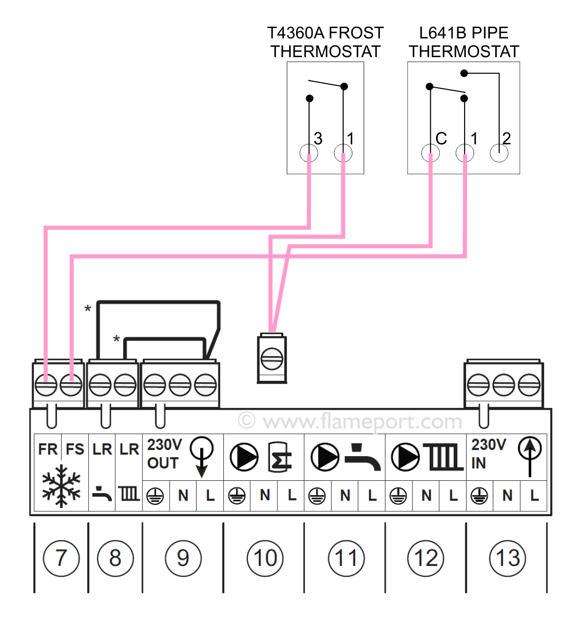
The choice will depend on the boiler. Connect the controls, pump, boiler and 230 volt fused supply to the junction box terminals indicated by the arrows in the diagrams next to each control, other electrical device or circuit. The g terminal on the existing thermostat must be connected to the furnace fan relay.
A wiring diagram is a simplified conventional pictorial representation of an electric circuit. Variety of central boiler thermostat wiring diagram. Greenstar ri (27kw and 30kw) wiring diagram.
Central boiler thermostat wiring diagram. Note a pump must be installed in the hot supply line between the outdoor furnace and thermostatic valve. It reveals the parts of the circuit as streamlined shapes, and also the power and signal links in between the tools.
It shows the elements of the circuit as streamlined shapes, as well as the power as well as signal links in between the gadgets. Wiring diagram for p/n 8200008 (forced air application) connect a wire from r on your existing thermostat to r on the additional thermostat then connect a wire from g on your existing thermostat to w on the additional thermostat. Wiring diagrams help technicians to see how the controls are wired to the system.
A wiring diagram is a streamlined standard photographic representation of an electrical circuit. If needed you can use flash amber. Assortment of central boiler thermostat wiring diagram.
Identify which terminals are the “r,” “w,” and “y,” and loosen each one with the screwdriver. Assortment of central heating thermostat wiring diagram. When using alternative wiring diagram, wiring instructions must be followed so power originates from the boiler aquastat.
Remove the motherboard of the old 2 wire thermostat and put the new 2 wire thermostat in its place. Test the 2 wire thermostat wiring by turning the furnace on. Mistakes made during thermostat wiring.
Honeywell thermostat rth2300b wiring diagram hook up the blue wire in the furnace cabinet where the blower section and the other thermostat wires are connected to the furnace. Repairing electrical wiring, a lot more than another household project is focused on safety. New wiring diagram for a system boiler thermostat wiring electric underfloor heating central boiler boiler control wiring diagrams wiring diagram is a simplified within acceptable limits pictorial representation of an electrical circuitit.
Intergas combi compact hre 2824 condensing combi boiler. Five ways to improve boiler efficiency: Essential tips for safe electrical repairs.
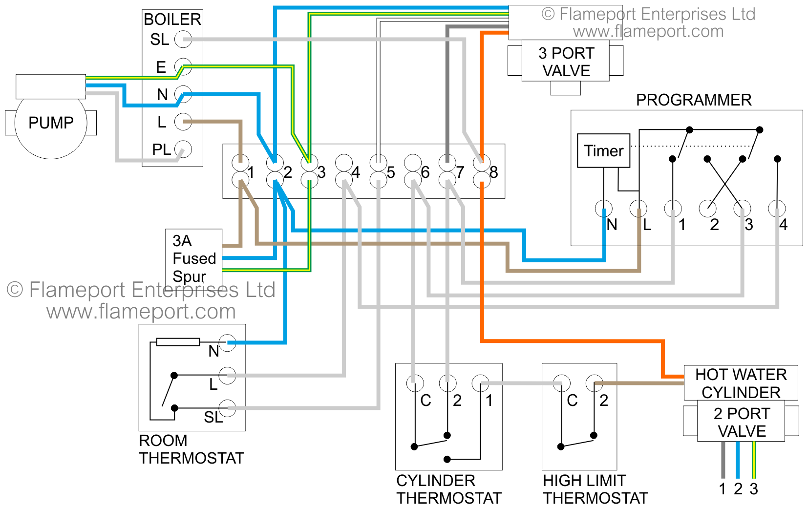
A wiring diagram is a streamlined standard pictorial depiction of an electric circuit. The sundial plan diagrams in this guide are designed for ease of wiring to a 10. When either the room thermostat or the cylinder thermostat calls for heat, it's eqivalent motorised valve opens and also turns on the boiler.
The circulator pump for the central heating is normally an intergral part of the boiler, so no additional wiring is required. This hardware is usually included with the boiler thermostat.

Honeywell S Plan Wiring Diagram 7

Boiler Wiring Diagram For Thermostat To Y Plan Hive New

Switchmaster Thermostat Wiring Diagram Creative Honeywell
Central Heating Thermostat Wiring Diagram


New Honeywell Central Heating thermostat Wiring Diagram
S Plan Wiring Diagram With Frost Stat Wiring Diagram and

Wiring Diagram Central Heating Programmer WORKINGMUSLIMAH

Htp Boiler Systems And Nest Wiring Diagram Nest Wiring

Pin on wireing

Luxury Wiring Diagram Combi Boiler diagrams
Wiring Indirect Hot Water Heater Zone Valve Diagram

Central Heating Circuit Diagram Advice Screwfix

S Plan central heating system Thermostat wiring, Central

Central Heating Thermostat Wiring Diagram

Danfoss Wiring Diagram Central Heating Central heating

Central Heating Wiring Diagram For Combi Boiler

Standard Control Thermostats Optimum Underfloor Heating
Central Heating Wiring Diagram For Combi Boiler

Navien Combi Boiler Wiring Diagram Download