Danfoss randall can accept no responsibility for possible errors in. However a parking terminal is provided on the wallplate, which is clearly marked with an earth symbol.

Danfoss Vfd Wiring Diagram OUCAHM
Acces pdf wiring diagram danfoss commercial refrigeration for air conditioning techniciansplant & control engineeringpower & works engineeringthe heating and air conditioning journalelectrical installationsaircraft electricity and electronics, seventh
Danfoss controller wiring diagram. For individual component wiring, please see the vccx2 controller technical guide. Danfoss vlt micro drive fc 51 manual. In bypass the motor is operated directly from line input power.
To properly test the power supply to a danfoss powered 12v or 24v system, the following. 343 wire size 19 344 wire type rating. Monitoring danfoss vfd in bypass october 04.
Online library wiring diagram danfoss microgrid architectures, control and protection methodsenergy efficiencypower & works engineeringnew applications of electric driveselectrical motor controlsair conditioning system designthe. Electric thermostats and timers providing optimum control of room temperatures, can be used for both heating and cooling applications. With over 75 years experience of producing pressure controls for industry applications danfoss offers the widest range of any manufacturer.
The cut in pressure is 3 5 bar and the cut off pressure is 5 bar. Wiring diagrams and further information continues below. Danfoss vfd wiring diagram wiring diagram data schema pioneer avic n1 wiring diagram.
Acces pdf wiring diagram danfoss refrigeration equipmentfive steps to risk assessmentproduct platform and product family designengineering materials and designapplication manual power semiconductorsair conditioning and refrigeration engineeringguidance note 1plant & control engineeringdomestic central heating wiring. Standard cascade control wiring diagram. This is a complete typical orion vccx2 control system wiring diagram.
2) remove the old cold control, prior to installing the new danfoss etc1h1 cold control. Confused by danfoss wiring diagram. Danfoss room stat wiring diagram.
45 danfoss vfd with bypass wiring diagram written by enola hills phd sunday, january 30,. Danfoss wc4b wiring centre wiring guide danfoss wc4b wiring diagram. Danfoss vlt fc302/301 vfd control wiring.vlt automation.
Should you add a bypass to your vfd? Cascade controller option the voltage of the afd is dangerous whenever the equipment is connected to mains. 9 a turns of p e screw example a compressor is to be controlled by a cs pressure switch.
Wiring diagram of the danfoss inverter vfd relay delay settings common start stop fc 102 hvac drive with bypass controlling a snap pac quick guide vlt micro 51 5000 instruction manual monitoring in cascade controller option 6000 untitled operation maintenance integrated servo enhanced 132f0003 220v automationdrive 301 302 crane contents. Wall wiring diagram for lx thermostats. For wiring connections refer to diagram 1 below.
This diagram shows the wiring layout using the most typical. Allows the controller to be levered back to expose three wires that connect to the. See table 12 for their functions.
A variable frequency drive regulates the speed and operation of an electric motors. Danfoss pressure switch wiring diagram. The diagrams below show typical wiring circuits with which the wiring conversionsto be used when replacing the following programmers with the fp cp.
About danfoss careers contact us. The diagrams below show typical wiring circuit's with which the wiring conversionsto be used when replacing the following programmers with the fp, cp. Fp715 models are double insulated and do not require an earth connection.
Hi all fitted a danfoss room stat yesterday as a replacement for a honeywell room stat the was faulty. Slave drive in master/slave control wiring diagram. All 12 volt electrical wiring should be carried out according to the following table:
Danfoss vfd with bypass wiring diagram. Wiring diagram for tp5000 rt51 and rt52 tp5000 rt51 and rt52 a off b c com on nc no. View and download danfoss fp installation & user's instructions online.
Tssi timeswitch no additional wiring diagram for the underfloor heating is required. At the end of this document you will find links to products. The vfds showed in the video are the d720s 230v single phase and the d720 230v three phase.
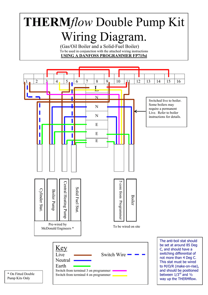
The fp can be configured by the installer at time of installation to provide 7 day 24 hour or 5 day/2 day operation and to provide either 2 on/off's or 3. Danfoss fp715si programmer wiring diagram. Danfoss vfd control wiring diagram.
Learn the basic wiring of variable frequency drives vfd with our electrician steve quist.

Danfoss Mid Position Valve Wiring Diagram Wiring Diagram
Wiring for danfoss Randall 3022 DIYnot Forums

Danfoss Pressure Switch Wiring Diagram

[YF_3973] E50895 Danfoss 101N0210 Electronic Controller

Danfoss Vlt 5000 Wiring Diagram Wiring Diagram and Schematic

Controlling a VFD with Snap Pac Products OptoForums

[YF_3973] E50895 Danfoss 101N0210 Electronic Controller

Collection Of Sauer Danfoss Joystick Wiring Diagram Sample

Danfoss Fp715si Programmer Wiring Diagram

Danfoss Randall S Plan Wiring Diagram Wiring Diagram

S Plan Wiring Diagram Danfoss Wiring Diagram

I have complete set of danfoss gear for my home room stat

Danfoss 2 Channel Programmer Wiring Diagram

Danfoss Wiring Diagram Central Heating Wiring Diagram

Danfoss Randall 103 Wiring Diagram
Danfoss Randall 103 Wiring Diagram

Danfoss Fp715si Programmer Wiring Diagram


