Usb connects the stereo to a usb source. Oct 14, · i was able to get my hands on the stereo wiring diagram for the 6 speaker fusion stereo.
Fusion Marine Stereo Wiring Diagram 21
Most stereos will power four speakers and each speaker needs a positive and negative wire.
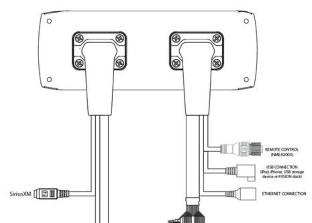
Fusion marine stereo wiring diagram. Connect the wiring harness to the stereo. Usb connects the stereo to a usb source. Á connects the stereo to the auxiliary in and line/subwoofer out wiring harness.
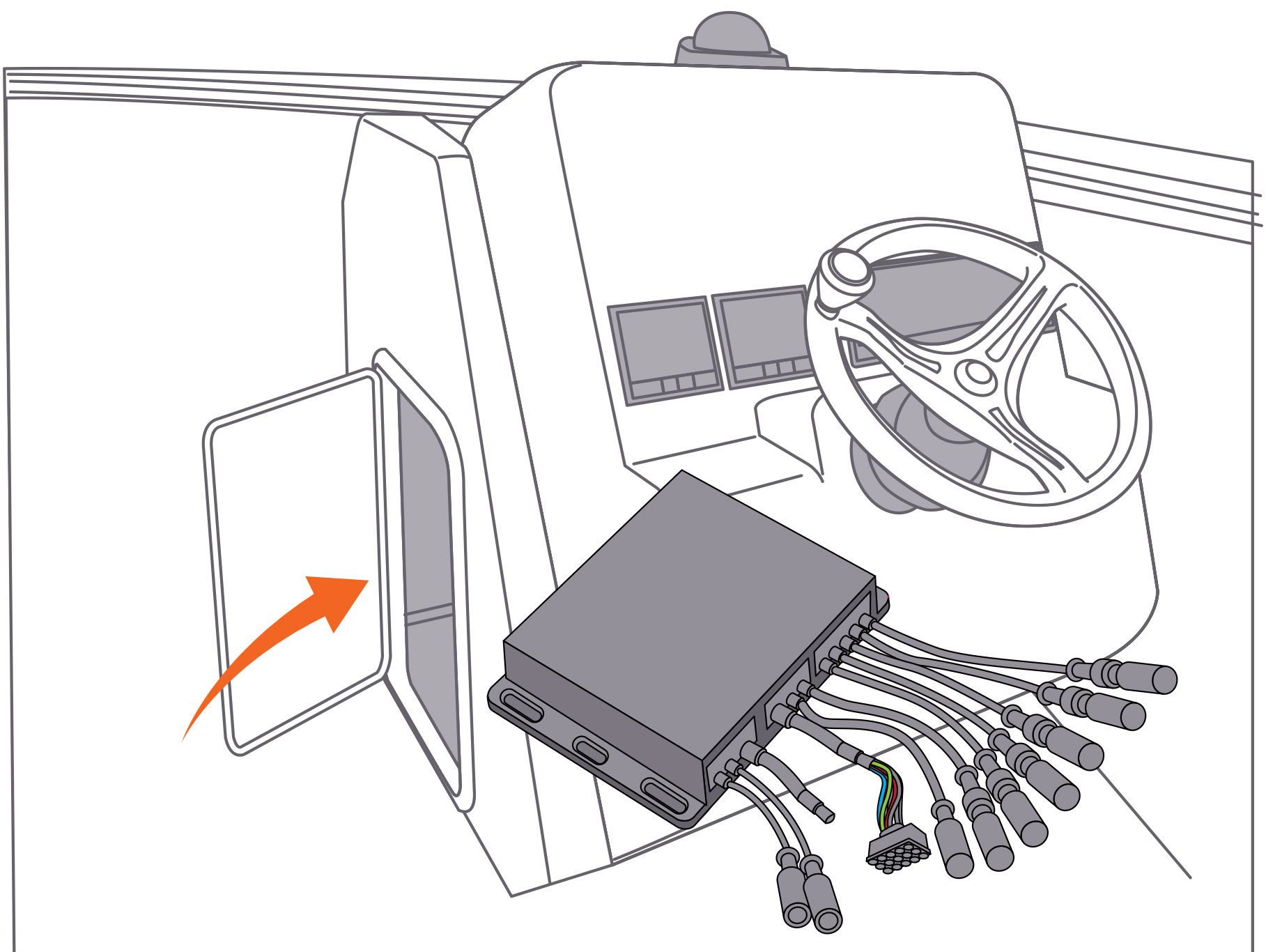
005 connections refer to the wiring diagram for reference pg 6 lineout lineout gives you the ability to connect a fusion marine amplifier. Garmin marine network wiring diagram. The black box systems offer compact entertainment solutions that blend both performance and subtlety where space is at a premium at the helm.
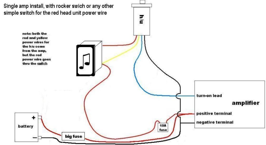
Select a location that allows both free/open airflow around rear of chassis, whilst minimising exposure to moisture. That eliminates most of the wires on the harness. Install all of the necessary fuses on the red and yellow wires.
Bmw e91 radio wiring diagram. The marine wired remote control the fusion marine stereo makes it possible to have 3 'zones', that refer to the wiring diagram for reference (pg 6). Vdo marine tachometer wiring diagram.
4 connect the red wire to the yellow wire, install a 15 a fuse ä The marine wired remote control extends the capabilities of the stereo by enabling local control of the audio in each zone of your vessel. Your new stereo will also have a wiring diagram in the manual so you can match up the wires.
Do not connect the wiring harness to the stereo until after you have made all of the bare wire connections. Bmw e90 radio wiring diagram. What is strange is that i've measured the voltage at the fusion wiring harness across the red/yellow and black wires (which are supposed to be 12v, 12v, and negative ground respectively).
Route all wires to the stereo wiring harness, the ignition or acc switch, the circuit breaker, and the power source as necessary. 2018 ford fusion se, speaker wire diagram? 2017 ford fusion tail light wiring diagram.
The fusion marine stereo makes it possible to have 3 ‘zones’, that have independent volume control. À connects the stereo to the power and speaker wiring harness. 5 connect the power wire to the ignition or another manual switch, and connect the switch to the positive (+) battery terminal if necessary.
See the device specifications for replacement fuse information. Any help would be greatly appreciated thanks!. The required wiring is supplied with the remote.
Inputs gain setup fusion amplifiers. 2017 ford fusion wiring diagram. Only) (nmea 2000 system wiring diagram, page 3).
Route all wires to the stereo wiring harness, the circuit breaker or switch, and the power source as necessary. Do not connect the wiring harness to the stereo until all of the bare wire connections have been made. For extensions longer than 1 m (3 ft.), use 12 awg (3.31 mm²) wire.
Install all of the necessary fuses on the red and yellow wires. To wire two 4 ohm speakers in parallel, to present a 2 ohm load per channel to a fusion 2 ohm stable amplifier, simply follow the below diagram showing the positive terminals from each speaker connected to each other and the same with the negative terminals. Nmea 2000 is available on fusion ms ra70nsx models only.
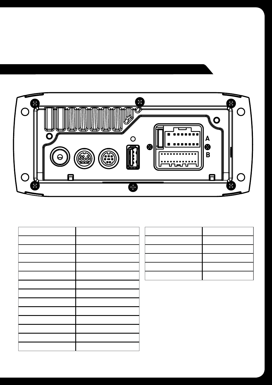
You must read all installation instructions before beginning the. Item description zone 2 speakers. See the device specifications for replacement fuse information.
Marine stereo wiring harnesses may look intimidating, but a simple explanation makes them easier to understand. Refer to the wiring diagram for reference appropriate mounting is very important to ensure correct operation. Do not connect the wiring harness to the stereo until after all of the bare wire connections have been made.
The 55 series is fusion’s most compact and competitive marine stereo with bluetooth audio streaming capability and clear, dynamic sound reproduction. Trying to convert a stock radio to accept and run an amp and subwoofer. 3 if you are routing the red wire through the ignition or another manual switch ã, connect the red ignition wire to the ignition or switch.
Refer to the wiring diagram for reference (pg 6) lineout lineout gives you. According to the manual these are the wires that are needed to power on the device. First check the voltage at the battery with the ignition in the off position.
Zone 1 and 2 are powered and can be linked, zone 3 requires a. Fusion ms ud750 wiring diagram. Just look up the wiring diagram.
(if available) and the volume control on the fusion marine stereo to set the volume level. Do not connect the wiring harness to the stereo until after you have made all of the bare wire connections. Fuse contains the fuse for the device.
Up to three remote’s can be linked to the stereo, via a canbus network, providing true system flexibility. 6 connect the wiring harness plug to the stereo. Fuse contains the fuse for the device.
Mercury marine control box wiring diagram. Eight of the wires on the harness are speaker wires. Consult this diagram to plan the wire connections.
The stereo has stopped powering on. If it is necessary to extend the red signal wire, use 22 awg (0.33 mm2) wire. Marine rocker switch wiring diagram.
Fusion Msud750 Wiring Diagram
57 Fusion Marine Stereo Wiring Harness Wiring Diagram


43 Fusion Marine Stereo Wiring Harness Wiring Diagram
Fusion Marine Amp Wiring Diagram Wiring Diagram and

Fusion Marine Amp Wiring Diagram Wiring Diagram and

57 Fusion Marine Stereo Wiring Harness Wiring Diagram
Fusion Marine Radio Wiring Diagram Wiring Diagram

51 Fusion Amplifier Wiring Diagram Wiring Harness Diagram


53 Fusion Marine Stereo Wiring Diagram Wiring Harness

Support Fusion Entertainment
Pyle PLCD6MRKT Marine and Waterproof Receiver


Fusion Marine Radio Stereo Wiring Harness Replacement

Fusion MSRA205 TrueMarine Stereo Free US Shipping
marine stereo amp wiring diagram Wiring Diagram and


Fusion Marine Radio Stereo Wiring Harness Replacement
53 Fusion Marine Stereo Wiring Diagram Wiring Harness
FUSION Apollo Zone Marine Amplifier Wiring Loom [01012814

Fusion Marine Amp Wiring Diagram Wiring Diagram and
Fusion Marine Amp Wiring Diagram Wiring Diagram and
