Typically, this is from a secondary receiving device such as a dcs or plc. Provides 1.3db of signal gain to compensate for any signal loss that may occur due to additional connections in the signal path;
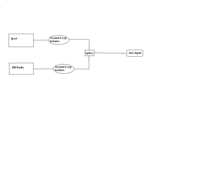
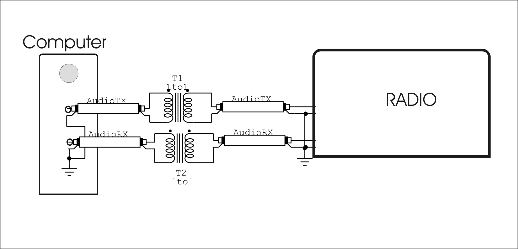
Ipod and XM wiring diagram through Ground Loop isolators
That wiring diagram is correct for a passive a/b, but it will not help avoid ground loops.

Ground loop isolator wiring diagram. Sadly, noise can be a big headache when it comes to car amps despite them being designed to prevent it. The output signal of the optocoupler is proportional to the light intensity of the. 45 kva transformer wiring diagram sample.
Optical isolation an optical isolation circuit has as operating principle two basic parts: Place the sam controller, amplifier, and ground loop isolator in proximity. In the drawing, outputs a and b share the same ground (the black wire connecting.
It is designed for applications where Sub panel ground bus neutral bus Not covered in this manual, please visit wiringall.com for more.
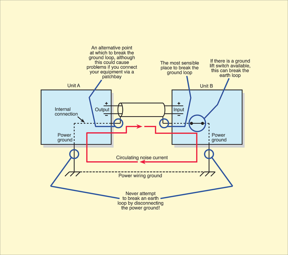
Connect the power wires to the aftermarket head unit. The voltage drops in the ground system caused by these currents are added to the signal path, introducing noise and hum into the output. Second version keeps earth currents away from the signal path as much as possible, reducing how much voltage perturbation.
It works by introducing a low dc voltage drop in that conductor. Because galvanic voltages and currents run below that level, the net effect is that galvanic current flow is stopped, effectively isolating your boat from your neighbors on the dock, at. 3 phase isolation transformer wiring diagram sample.
Brown wires are optional grounds if you are not getting an audio signal; Electrical isolation provides safety, so that a fault in one area does not damage another. Isolated ground transformer wiring diagram.
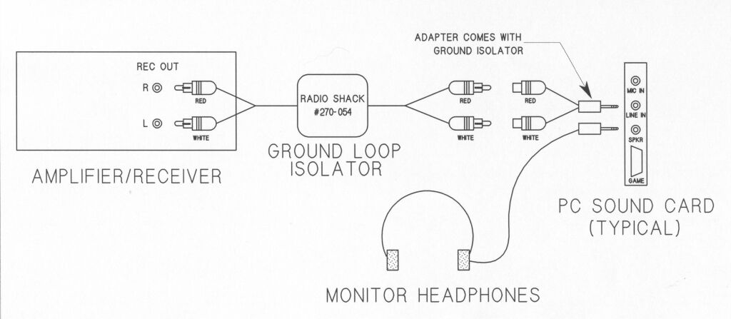
You can eliminate the problem in your system by adding a rca ground loop isolator. The amplifier must be mounted within 10 inches of the isolator unless a cable extension is used on the isolator pigtail (for details, see audio harnesses on page 17). In any case, i think that the dock is just a passthrough on all the pins from the rear to the dock itself, and then simply breaks out the line output pins to the stereo jack connector.
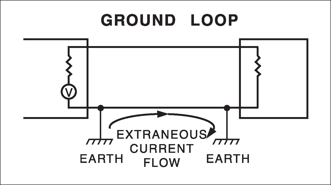
This creates inadvertent closed loops in the ground wiring circuit, which can allow stray 50/60 hz ac current to be induced and flow through the ground conductors of signal cables. Isolated ground isolated grounded receptacle has an isolated terminal from the yoke to the ground lug. A simple ground isolator fixes it, of course, but it's something to keep in mind when installing into your car, as a ground loop is a lot easier to achieve there.
A transformer in the power supply provides magnetic isolation between the primary and secondary sides. Use when noise is caused by ground loop through patch cords; These receptacle are usually marked with an orange triangle or all orange.
Ground the ground loop isolator by screwing the terminal into a bare metal spot of the car or by plugging it in to the negative terminal of the amp. Collection of isolation transformer wiring diagram. But what we apparently should be using is this:
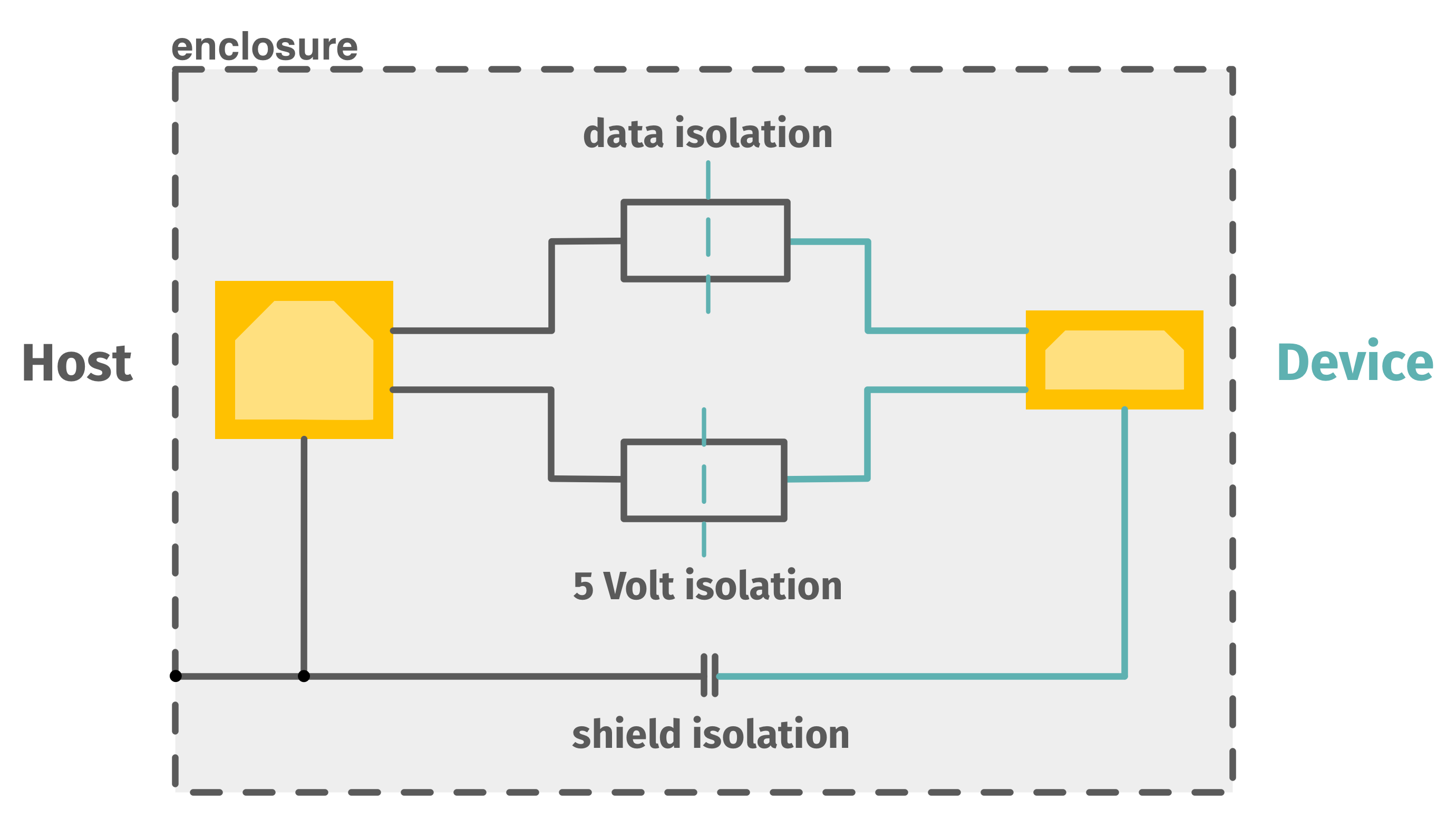
The galvanic isolator is installed in the green grounding conductor in your shore power system. Color function black ground yellow battery/memory red ignition/accy blue power antenna blue/white amplifier turn on note: Dl405 system circuitry is divided into three main regions separated by isolation boundaries, shown in the drawing below.
Since the power supply provided by the power distribution function of the control system input module (or input of instrument) is not isolated from the input terminal, the output signal of the power supply mode. Principles of electrical grounding john pfeiffer, p.e. This system is unfortunately quite sensitive to radio interference, so the 100 ohm resistor is usually shunted with small capacitor (usually 4pf to 10 nf) which makes the impedance to be low at radio freqwncies but does not let too much 50 hz current flowing.
The loops can include the building's utility wiring ground system. Connect the rca cables to the line outputs on the aftermarket head unit or use metra's Plug one end of the ground loop isolator into the rca input on the back of the buttkicker power amplifier and then plug the rca cable coming from your a/v processor into the other end of.
Plugs in at head unit end of rca cables; Finally you can now back fill your loops with the remaining clay and soil you had removed, ensure the ground is fully compacted to remove air voids. A ground loop isolator you can use to “break” (isolate, disconnect) an amp’s rca ground connections from that of an audio source to eliminate the electrical path that causes ground loop noise.
Gnd ground equipment enclosure ig receptacle if used main breaker receptacle panel no scale receptacle wiring diagram isolated ground. This resitor limits the current passing in the ground loop situation, but still provides quite good ground connection. Isolated ground transformer wiring diagram wiring diagram and schematics wiring diagram and schematics this place is a growing library of the schematics,.
A ground loop occurs when the two amps see more than one path to ground, and when you split with a common signal ground like this, you will create a second path to ground.
D.I.Y. AuxIn on 2007 W203 (without the wiring harness
How To Eliminate Ground Loops With Signal Isolation

The Ins and Outs of Isolation A Guide to Selecting The

Ground Loop Isolator Schematic cleverku
Diy Ground Loop Isolator / Coaxial Video Ground Loop
Wilkerson Instrument Company Inc. Blog » Ground Loop Diagram
Curing Ground Loops
USB Isolator CESYS Gesellschaft für angewandte
![]()
Isolated Ground Transformer Wiring Diagram Wiring Diagram
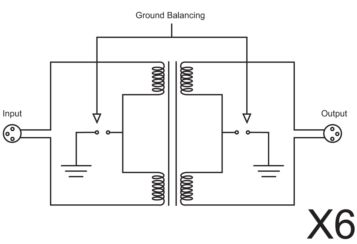
Sonifex RBPLI6 6 Way Mono Passive Line Isolation Unit
Pesky Ground Loop Problems Plaguing You? ProSoundWeb
audio Reduced gain with ground loop isolation with car
Audio Transformer Wiring Wiring Library
CCTV Camera Video Ground Loop Isola (end 4/8/2019 104 AM)


Electrolab How to make car audio/stereo (mp3/bluetooth
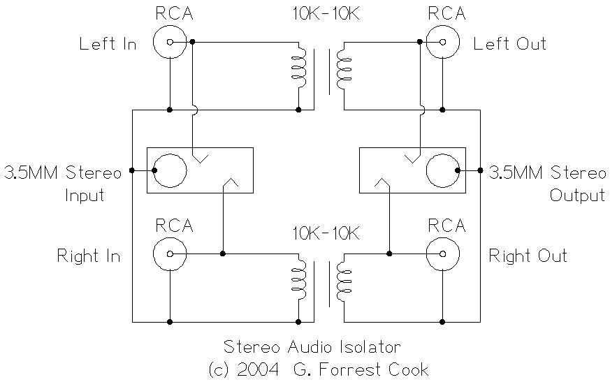
Stereo Audio Isolator
What is a ground loop? Jensen Transformers
Optically Isolated Usb Hub Wiring Diagram USB Wiring Diagram


☑ Grounding Capacitor And Amp