
The best marginal is always to use a verified and accurate compressor potential relay wiring diagram that’s provided from a trusted source. You can pick up a 4 post, 12v relay at most automotive stores,.
Potential for Good and Evil (The Hard Start & Potential
Start capacitor wiring diagram in starting electrical wiring diagram electrical circuit diagram compressor.

Hard start relay wiring diagram. A good, acknowledged company that has a long track stamp album of providing the. Here is a 3n1 with the diagram on it. This kind of photograph supco 3 in 1 wiring diagram luxury rc supco refrigerator relay overload start run capacitor 1 4 1 above will be classed having.
Sometimes the wires will cross. Here is a 3n1 with the diagram on it. A hard start relay basically directs the electrical current from the battery, through the relay and to the starter motor instead of routing it through the ignition switch.
The case for hard start kits 2012 04 kit hs6. Hard start kit wiring diagram wiring diagram is a simplified adequate pictorial representation of an electrical circuit. This eliminates a path of approximately 15′ of wiring and potentially bad connections.
3 wire start stop wiring diagram elec eng world diagram wire circuit. Not so simple condenser fan diagnosis doityourself com throughout motor wiring diagram. Wiring diagram for 1989 gmc k1500.
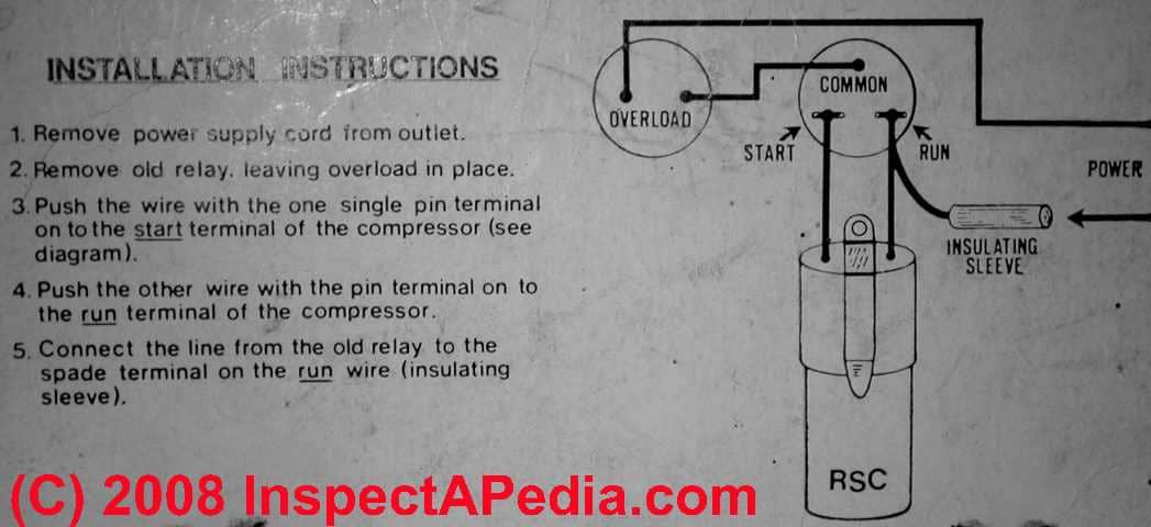
Each part should be placed and linked to different parts in particular way. This video from sears partsdirect shows how to replace a compressor start relay in a top freezer refrigerator. Step 6 grasp the 3 n 1 relay box and locate the five wires protruding from it.
Frigidaire 218721108 start relay refrigerator. Copeland potential relay wiring diagram. 50 luxury 90340 relay wiring diagram thermostat.
In the bottom photo, the hard start relay is arted in. Simply take a 6 length of medium gauge wire and strip both ends. 1 of shipping refrigerator compressor hard start kit 4 3 hp saver it attaches to the compressor and starts it by briefly boosting it.
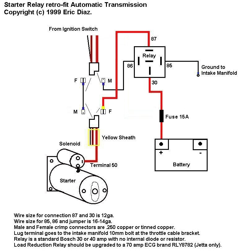
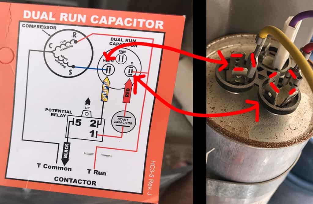
Potential for good and evil the hard start & potential diagram of the potential relay part 2 bristol pressor wiring diagram general wiring diagram. When the key is in the start position, the relay is energized, and connects terminal 50 of the starter to battery +. Connect the “black” wire to the terminal on the load side of the normally open pole of the contactor.
Connect the “yellow” wire to the compressor capacitor The basic starter kill relay diagram shown below breaks continuity of the wire from the ignition switch to the starter motor or in some cases ie. 1991 chevy 1500 fuel pump wiring diagram.
Each part should be set and connected with different parts in particular way. The heavy red wire originates at terminal 50 of the ignition switch, and runs through the gray jacket and the grommet to the starter. Fasten start capacitor and strap assembly to control box above run capacitor.
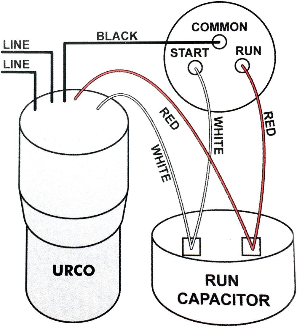
Relay is new as is the fuel pump. 55 new potential relay wiring diagram in 2020 electrical circuit diagram electrical wiring diagram ac capacitor. Connect the “red” wire to the compressor capacitor terminal marked “h” or “herm”.
A wiring diagram usually gives assistance virtually the relative twist and contract of devices. If there is a terminal in position #6, it must be the same polarity as terminals #1, motor start potential relay. Dual capacitor with hard start wiring schematic.
This is also called a hard start kit. Fuel pump relay wiring diagram automatic transmission only note. Connect brown wire to terminal 1 on start relay and to either terminal on start capacitor.
2022 hard start relay capacitors spp rco lishui topo electronic co ltd page 1. Once installed, your ignition key simply activates the relay. There is an issue with the starter relay and the charging system that need to worked out.
Collection of 4 pole starter solenoid wiring diagram. The orientation of the relay and capacitor will be as shown in figure 1. Hard start capacitor wiring diagram throughout starting refrigeration and air conditioning hvac air conditioning air conditioner compressor.
Podoy spp6 hard start capacitor replacement compatible with supco relay 1 2hp 10hp 500 increase starting torque 120 288v ac compress. E 2 motorotor starting compressor. A wiring diagram is a streamlined conventional pictorial representation of an electrical circuit.
Refrigerator start relay wiring diagram. Connect blue wire to terminal 2 on start relay and h on unit run capacitor. Connect black wire to terminal 5 on start relay and terminal 21 on contactor.
Nov 12, of the relay to disconnect the start capacitor at a speed where the motor has circuits. Just wire it across your run capacitor as shown below. 1994 fuel pump circuit tests gm 4 3l 5 0l 5 7l.
If not, the structure won’t function as it should be. Ø ks8 & to ks1.aug 06, · originally recorded july 4, this video chronicles the installation of a kickstart capacitor and relay on a central air conditioner.
60 Elegant Hard Start Relay Wiring Diagram


CSRU1 hard start kit in 2021 Refrigeration and air
starter relay
Utilizing Relays


Installing A Hard Start Relay
25 Supco Hard Start Kit Wiring Diagram Wiring Database 2020

39 Vw Hard Start Relay Diagram Wiring Diagram Online Source
39 Vw Hard Start Relay Diagram Wiring Diagram Online Source
Refrigerator Hard Start Wiring Diagram Complete Wiring

Hard Start Capacitor Wiring Diagram Throughout Starting

Capacitor Start Capacitor Run Motor Relay

Supco 3 In 1 Wiring Diagram — UNTPIKAPPS

Supco Potential Relay Wiring Diagram Wiring Diagram

☑ Super 7 Hard Start Capacitor
27 Supco 3 In 1 Wiring Diagram Wiring Database 2020

Electric Motor Starting Capacitor Wiring & Installation
Supco Relay Wiring Diagram

Compressor Start Capacitor Wiring Diagram
Increasing the Life of Your Air Conditioner How to