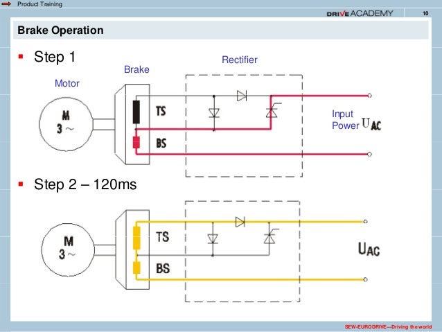
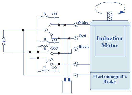
The rectifier energizes the brake coil. There’ll be principal lines which are represented by l1, l2, l3, and so on.
Replacing clutch and motor brake rectifiers with KEB
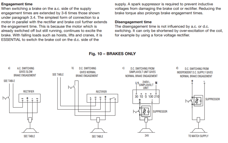
The brake will release and allow the motor to rotate when the nameplate ac brake voltage v b is supplied to the brake rectifier terminals.
Sew brake rectifier wiring diagram. The brake coil attracts the stationary disc, removing pressure between stationary disc and brake disc. The supply voltage for brakes with an ac connection is either supplied separately or taken from the supply system of the motor in the wiring space. 2.brake springs create pressure between stationary disc and brake disc.
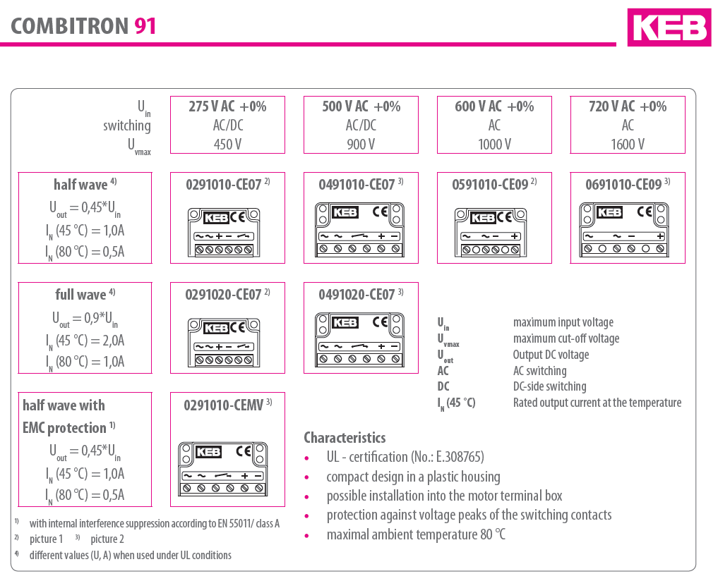
Refers to the brake preventing rotation of the motor despite loss of power The different housings for the brake rectifiers have different colors (= color code) to make them easier to distinguish. For brake connections, see the following pages.
This manual provides information on brake rectifiers along with typical connection diagrams for nord motors with brakes. However, please check immediately upon arrival for accordance with the wiring diagram, which can be found in the terminal box. The brake can also be released mechanically if equipped with a manual brake release.
Wiring diagram for basic unit movidrive® b brake rectifier in the control cabinet install the connection cables between the brake rectifier and the brake separately from other power cables when installin g the brake rectifier in the control cabinet. The supply can come from the motor line. Occasionally, the cables will cross.
It functions like the rectifier type bg, however, it is designed to be mounted ina controlpanelon dinrail andnot inthe motorsconduit box.thebms canbewiredtooperate for normalorrapid brake reactiontimes.thebmsrectifier The brake coil attracts the stationary disc, removing pressure between stationary disc and brake disc. The recommended ring terminals are manufactured by thomas & betts or equivalent.
As stated earlier, the lines at a rectifier regulator wiring diagram signifies wires. • only suitable for sew brakes that are dimensioned for the supply voltage of the g120d. It is not intended to include a comprehensive listing of all details or procedures required for installation, operation, maintenance or troubleshooting.
The wiring diagrams for brake connections are located on the inside of the motor conduit box lid. According to the sew connection diagram you only need the 2 phases from the motor windings to operate the rectifier, so when the motor gets the voltage to drive the brake releases. 5 12 3 4 5 6 7 8 9 10 11 12 to the brake coil:
2.4.1 normal starting (bg) the bg rectifier provides normal starting, which is sufficient for most applications with low or infrequent cycling. The supply voltage for brakes with an ac connection is either supplied separately or taken from the supply system of the motor in the wiring space. It meets the basic safety requirements.
Brake control in the wiring space. 02280axx screw the current/voltage relay sr/ur with gasket into pg16 in the is lower section. The supply can come from the motor line.
Friction stops motor and prevents it from rotating. Frontrear brake light switch replacement. Screw on the brake rectifier again (with washers).
I also tried swapping a know good rectifer to test it out but the brake didnt release still. Brake springs create pressure between stationary disc and brake disc. The different housings for the brake rectifiers have different colours (= colour code) to make them easier to distinguish.
Gear motor unit s37 dre80m4 / kw / kw /v/50hz ip55 diagramweb.netf rp 5,,/pc weeks gear motor unit s37 drs71m4. Nord utilizes brakes manufactured by precima and mayr. Injunction of 2 wires is usually indicated by black dot at the junction of two lines.
The rectifier energizes the brake coil. White red blue wh bl rd In addition, they may be wired for either normal or rapid stopping.
The brake is applied when the voltage supply is interrupted. Brake service and maintenance| training department february 19, 2016. 6 2018 common connection diagrams 2.4 brake control sew brakes are available for either normal or rapid starting.
When connecting the supply power from the motor terminal block to the brake rectifier, follow the specifications below. For wiring the upper section of the is plug connector (part number 184 424 5), refer to the ac motors/ac brake motors operating instructions. Brake control in the wiring space.
However, it doesn’t mean link between the cables. There are certain cases where the brake rectifier can receive its voltage from the motor’s
Brake rectifier Electric motors & generators engineering
Sew Eurodrive Motors Wiring Diagram For Your Needs

31 Sew Eurodrive Brake Diagram Sewing Information

Sew Eurodrive Motors Wiring Diagram

34 Sew Eurodrive Brake Diagram Sewing Wiki Source
43 Sew Motor Wiring Diagram Wiring Niche Ideas
37 Sew Eurodrive Motor Wiring Sewing Wiki Source

Seweurodrive Wiring Diagram

why is my 3 phase motor turning at 42 of rated rpm?

SEW EURODRIVE 2015

29 Sew Eurodrive Motor Wiring Diagram Wiring Database 2020

Sew Eurodrive Wiring Diagram

Wiring Diagrams Brake Rectifiers and Coil Data
Patent US5278483 Motor brake with single free wheeling


Sew Eurodrive Wiring Diagram

Sew Eurodrive Motor Wiring Diagram

Sew Eurodrive Wiring Diagram

Patent US5408154 Motor connection block, particularly

Brake rectifier Electric motors & generators engineering