In the electrical forum area at electriciansforums.net. We strongly recommend using a.
3 Phase Contactor Wiring Diagram Start Stop Cadician's Blog
This guide even consists of suggestions for added materials that you may require to be able to finish your projects.

Start stop wiring diagram. A wiring diagram is a streamlined conventional photographic representation of an electric circuit. Wiring diagram for motor starter 3 phase controller failure relay electrical pleasing three electrical wiring electrical circuit diagram home electrical wiring. Wiring diagrams for the various configurations are below.
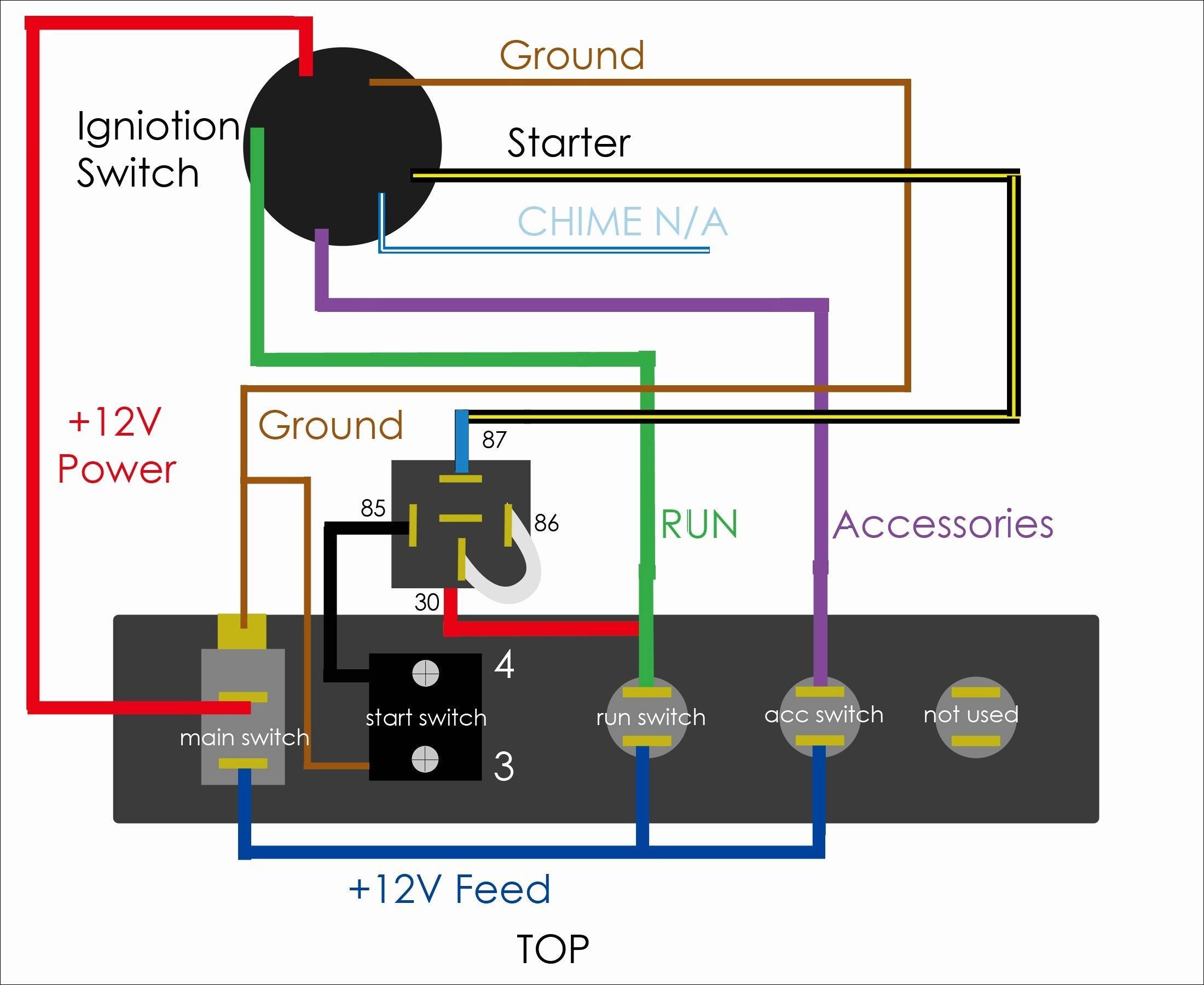
How does vfd start stop wiring diagram work. Vfd start stop wiring diagram: Basic control motor, to get start or stop the motor, use a push button switch as a trigger a motor.
With the use of the vfd not only saves energy but also saves the life of motors by providing a soft start and advanced process control. Vfd start stop wiring diagram. With the switch closed the control circuit acts as a normal stopstart station controlling a load connected to the pilot device power is sitting on the start and seal in terminals of the pushbutton.
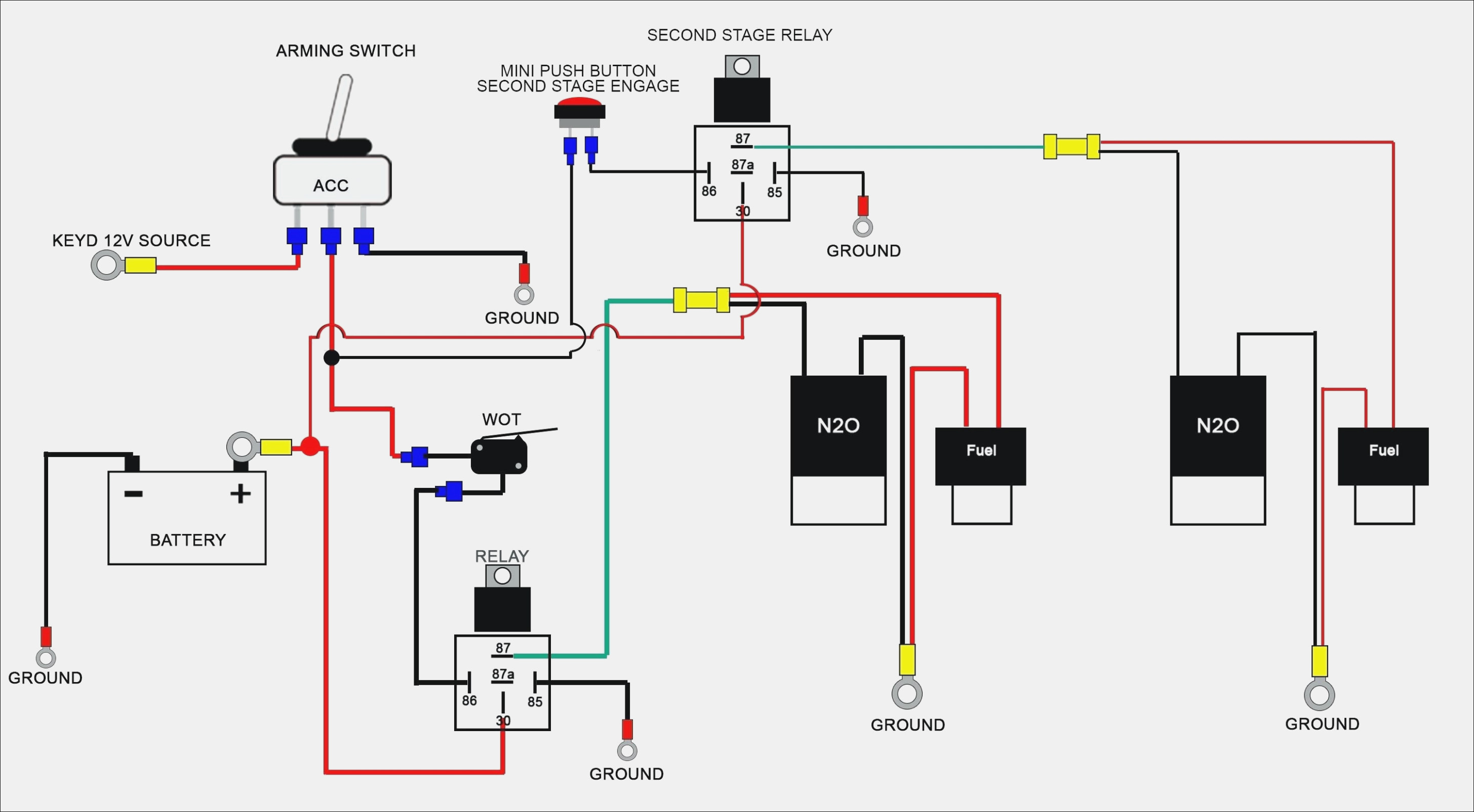
Injunction of 2 wires is usually indicated by black dot in the intersection of 2 lines. 21 unique generac automatic transfer switch wiring diagram from fjelloghjem.blogspot.com. The block diagram for the vfd below shows typical control switches.
Wiring diagram will come with numerous easy to stick to wiring diagram instructions. The other thing that you will see a circuit diagram would be lines. It’s meant to help each of the common user in developing a suitable method.
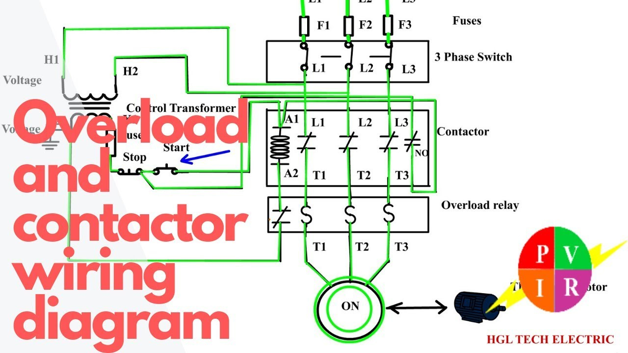
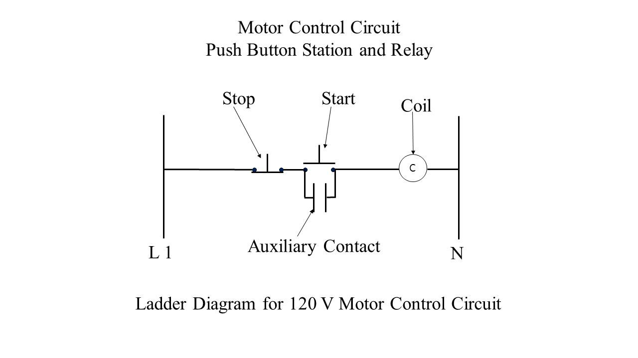
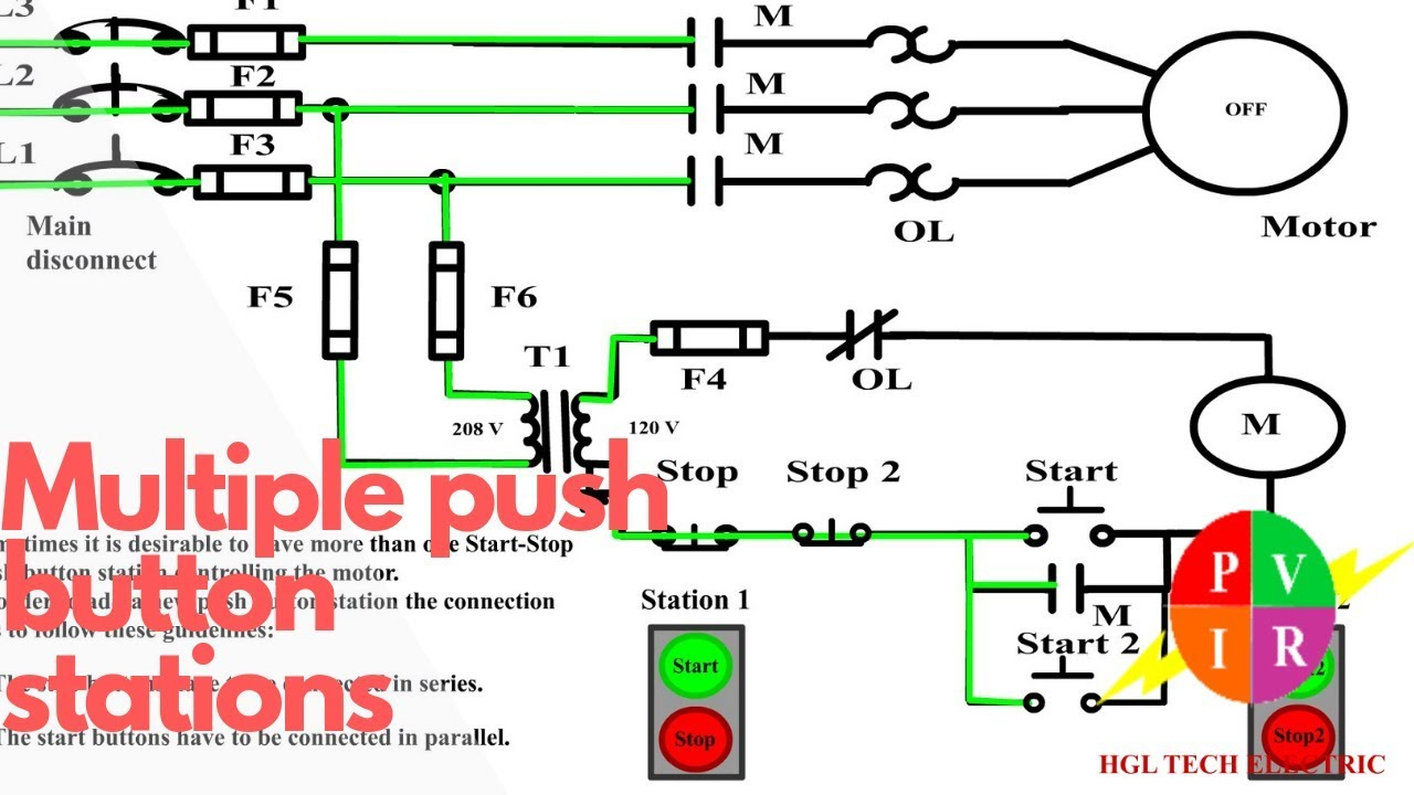
Ladder diagram basics 4 multiple stop start stations. 3 wire start stop wiring diagram elec eng world diagram wire circuit. When you press the start button and the stop button is not pressed, the 24vdc relay energizes and it pulls in the r1 contactor that feeds three phase power to the motor.
Start stop 3 wire control. A circuit is usually composed by many components. Considering grating to remove, replace or repair.
However, it doesn’t mean link between the wires. At times, the wires will cross. Push to make / ptm switch use to start the motor and push to brake / ptb switch use to stop the motor.
These directions will probably be easy to comprehend and apply. Wiring diagram for start/stop ? There are two things which are going to be present in any motor starter wiring diagram start stop.
Tags button circuit contact diagram start wiring wiring diagram discuss wiring diagram for start/stop ? I am here with giving you a vfd start stop wiring diagram for running a vfd through panel board push button and keypad of the vfd it is called hmi. This video is a step by step explanation of wiring start stop basics.
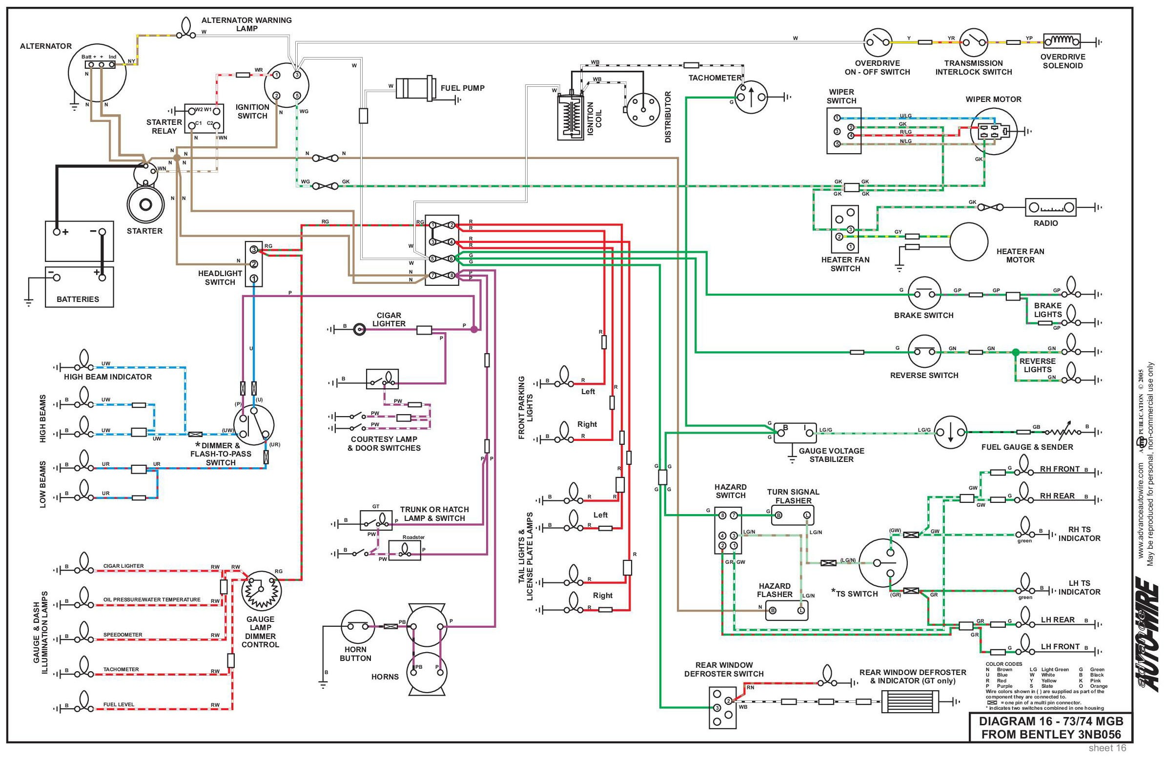
We are happy to explain further or talk about custom options if you don’t see what you’re looking for. The generator must have start and stop controls [e.g., electric starter and electric choke (for wiring diagram auto electrical wiring diagram drawn by checked date scale sheet no. Home decorating style 2020 for 3 phase start stop wiring diagram, you can see 3 phase start stop wiring diagram and more pictures for home interior designing 2020 180206 at manuals library.
Through the thousands of photos online about 3 phase start stop wiring diagram, selects the best libraries with ideal resolution only for you, and this pictures is actually among graphics series within our very best photos gallery regarding 3 phase start stop wiring diagram. 3 phase contactor wiring diagram in 3 phase start stop wiring diagram diagram fuse box how to find out Motor starter schematic and wiring diagram.
Start stop switch wiring diagram source. I am here with giving you a vfd start stop wiring diagram for running a vfd through panel board push button and keypad of the vfd (it is called hmi). Vfd start stop wiring diagram:
Posted on may 14, 2018 august 9, 2018 by headcontrolsystem. According to earlier, the lines at a start stop push button wiring diagram signifies wires. Used to disable the auto start circuit from starting the generator.
Push to make / ptm switch use to start the motor and push to brake / ptb switch use to stop the motor. Wiring diagrams september 04, 2021 16:07. The wiring diagram for connecting thee phase motor to the supply along with control wiring is shown in figure below.
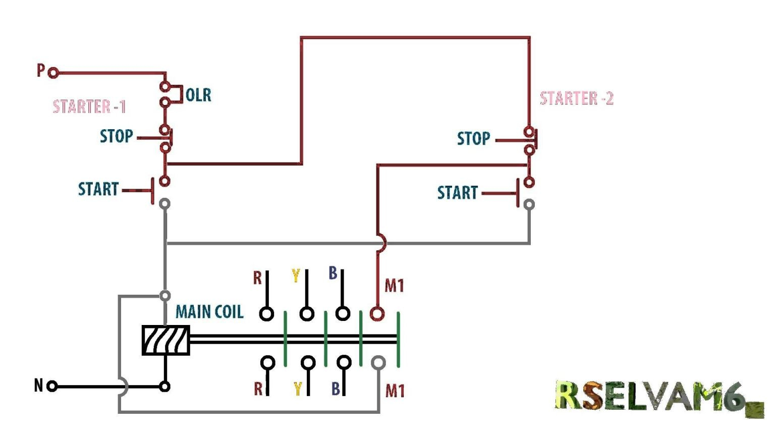
Wiring diagram book a1 15 b1 b2 16 18 b3 a2 b1 b3. Motor control can be done with a plc program. Typical wiring diagrams for push button control stations 7 start stop control wiring diagrams single station with motor stopped pilot light l1 start l2 i 1 stop 2 oi 3 n wol.
They are used in applications which do not require undervoltage protection. Vfd is a short form of variable frequency drive or variable voltage variable frequency drive.the vfds are working based on changing the input frequency and input voltage of the motor, we can change. With such an illustrative manual you will be capable of troubleshoot stop and total your projects with ease.
The first component is symbol that indicate electric element from the circuit. The difficulty essentially is that all car is different. Vfd start stop wiring diagram.
If you are unsure, please feel free to contact us. The most common use of 3 wire control is a start/stop control. Wiring diagram single motor with start stop switch basic control motor to get start or stop the motor use a push button switch as a trigger a motor.
Wiring diagrams do not show the operating mechanism since it is not electrically controlled. See image below for an example of 3 wire control being used to pull in a contactor to start a 3 phase motor. Start date feb 11, 2012;
Wiring diagram also gives beneficial recommendations for projects which may need some extra tools. As long as you follow the ladder diagram and take it one wire at a time its simple.this. Pilot light l2 4 2 3 pilot light start stop bulletin 1495 normally closed auxiliary contacts are required.
Start Stop Push Button Wiring Diagram Wiring Diagram
Motor Starter Wiring Diagram Start Stop Cadician's Blog

Start Stop Wiring Diagram Free Wiring Diagram

Contactor Wiring Diagram Start Stop For Your Needs
Start Stop Push button Wiring Diagram Single Phase Awesome

Two Wire & Three Wire Motor Control Circuit Motor

Stop Start Motor Starter Wiring Diagram Complete Wiring
Start Stop Push Button Wiring Diagram for Android APK
3 Wire Start Stop WiringDiagram Elec Eng World Wire

Start Stop Wiring Diagram Free Wiring Diagram
Push Button Starter Switch Wiring Diagram Wiring Diagram
Start Stop Push Button Wiring Diagram Wiring Diagram

Start Stop Push button Station Wiring Diagram Collection

Start Stop Button Wiring Diagram / Diagram Starter Relay
45 Start Stop Push Button Wiring Diagram Single Phase

35 Start Stop Wiring Diagram Wiring Diagram Database
Start Stop Jog Circuit Motor Control Circuit Diagram

Start Stop Contactor Wiring Diagram Wiring Diagram And
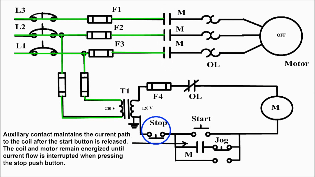
Jogging control circuit. Jog motor control. Start stop and