Abb capacitor banks series 100, 300, 500, 700, 300r and 500r Capacitor bank, detailed instructions for these components are included in the.
☑ Connection 3 Phase Capacitor Bank Wiring Diagram
Capacitor bank control wiring diagram.
Capacitor bank wiring diagram. An unbalance protection device (current relay and transformer) continuously monitors the unbalance current between two neutral points. 3 phase capacitor bank wiring diagram sample. The best marginal is always to use a verified and accurate power factor correction capacitor wiring diagram that’s provided from a trusted source.
In the delta, the line voltage is equal to the phase voltage. 8 9 2018 increase of 3 phase capacitor bank wiring diagram a wiring diagram is a simplified satisfactory pictorial depiction of an electric circuit it shows the elements of the circuit as simplified shapes and the gift as with ease as signal links amid the gadgets. As shown in the above figure, 2 capacitor banks have been connected to the grid.
All the arrangements in electrical pomes system are done to meet up this basic requirement. All these are connected in delta. It includes directions and diagrams for various varieties of wiring techniques and other products like lights, home windows, etc.
Three phase capacitor bank wiring diagram. The capacitor bank will be launched as a new product of the company, so it is necessary to meet all the standard`s requirements in terms of the elements, dimensions, connections, cross section of the wires, capacitor protection since it needs to be tested and accepted by certified laboratory. A wiring diagram is a simplified standard pictorial depiction of an electric circuit.
It shows the elements of the circuit as simplified shapes, and the power as well as signal links between the gadgets. Use the fa ctory order number found on the nameplate for reference. Electric motor starting capacitor wiring installation.
Sizing for power factor correction electrical. If not, the structure will not. Conductor size can be determined from a wire size chart.
The real truth behind household power savers. Make sure that the circuit matches the actual motor diagram before applying capacitors. Generally, the unit of a capacitor bank is known as a capacitor unit.
The schematic diagram for a permanent split capacitor motor is shown in fig. If switches are provided with the capacitor bank, the switch contacts must remain closed during transportation and handling. Wiring of power factor relay on lv and mv side circuit diagrams eep.
11 kv capacitor bank tepco scientific diagram. The diagrams below show capacitor connections for typical starting circuits for reduced voltage motor controllers. It shows the components of the circuit as simplified shapes, and
Connection diagrams for factor correction capacitors kvar guide the circuit diagram of single phase power system scientific. Test and operate all switches and secondary accessory equipment. Capacitor leakage tester circuit find.
Capacitor bank capacitor bank types. The demand for active power is expressed in kilowatts (kw) or mega watts (mw). The capacitors should only be on line when the load requires kvar and disconnected when the load is reduced.
In an low voltage electrical installation, capacitor banks can be installed at three different levels: Capacitor bank | reactive power compensation. 3 phase capacitor bank wiring diagram sample.
This helps in improving the power factor. Read mitsubishi mini split wiring diagram. Installation options for capacitor banks.
Kvar unit wiring diagram implementation of capacitor banks electrical. Each component ought to be placed and linked to different parts in. 2 circuit diagram of power factor improvement and controller scientific.
Ensure the capacitor bank frame is properly grounded per utility grounding practices. Contact your nearest schneider electric field office to replace lost or damaged wiring diagrams and instruction sheets. Each component should be placed and connected with other parts in particular manner.
2008 ford escape blower motor resistor 2010 ford escape blower motor resistor 3 phase diode bridge rectifier 5 wire ceiling fan capacitor wiring 5 wire ceiling fan capacitor wiring diagram 650nm laser diode datasheet audio coupling capacitor audio coupling capacitor value camera flash capacitor charging circuit capacitor cbb61 250vac 50/60hz The wire size from the auxiliary capacitor bank to the 3 ph motor may be determined by the following formula which will calculate the amperage rating of the circuit. Collection of 3 phase capacitor bank wiring diagram.
Cx power factor control relay. The recommended wire size is. This power should be supplied from electrical generating station.
4 abb capacitor banks series 100, 300, 500, 700, 300r and 500r | low voltage capacitor banks the abb capacitor bank: The circuit diagram of the 555 timer in astable mode is shown below. A wiring diagram typically offers details about the…
Discharge behavior of capacitor banks
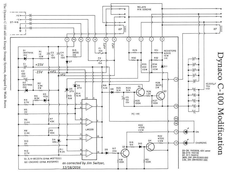
3 Phase Capacitor Bank Wiring Diagram Seputar Bank
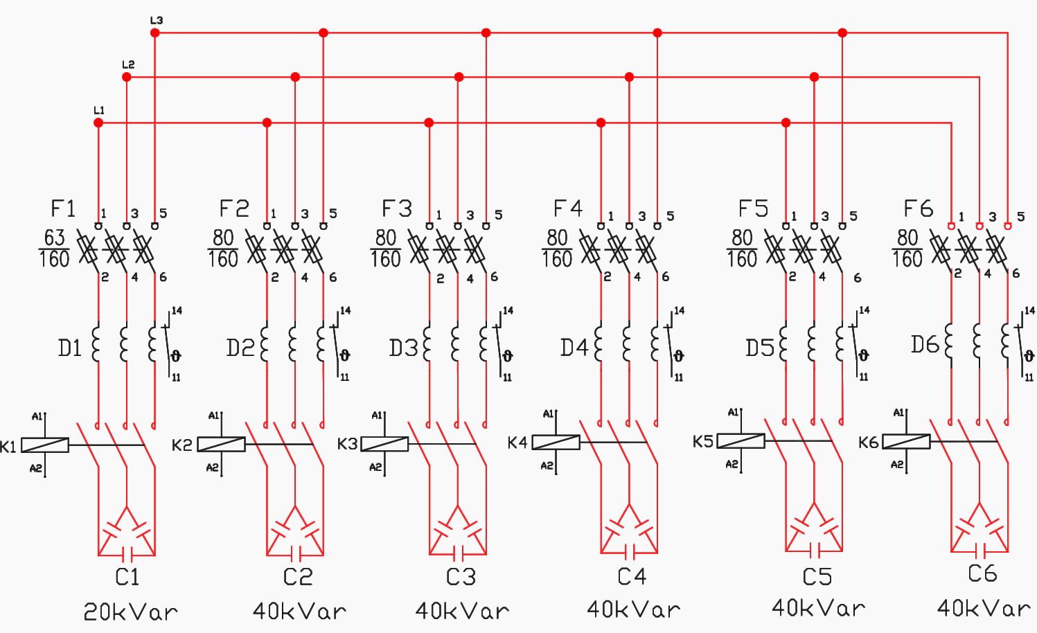
Stepbystep tutorial for building capacitor bank and
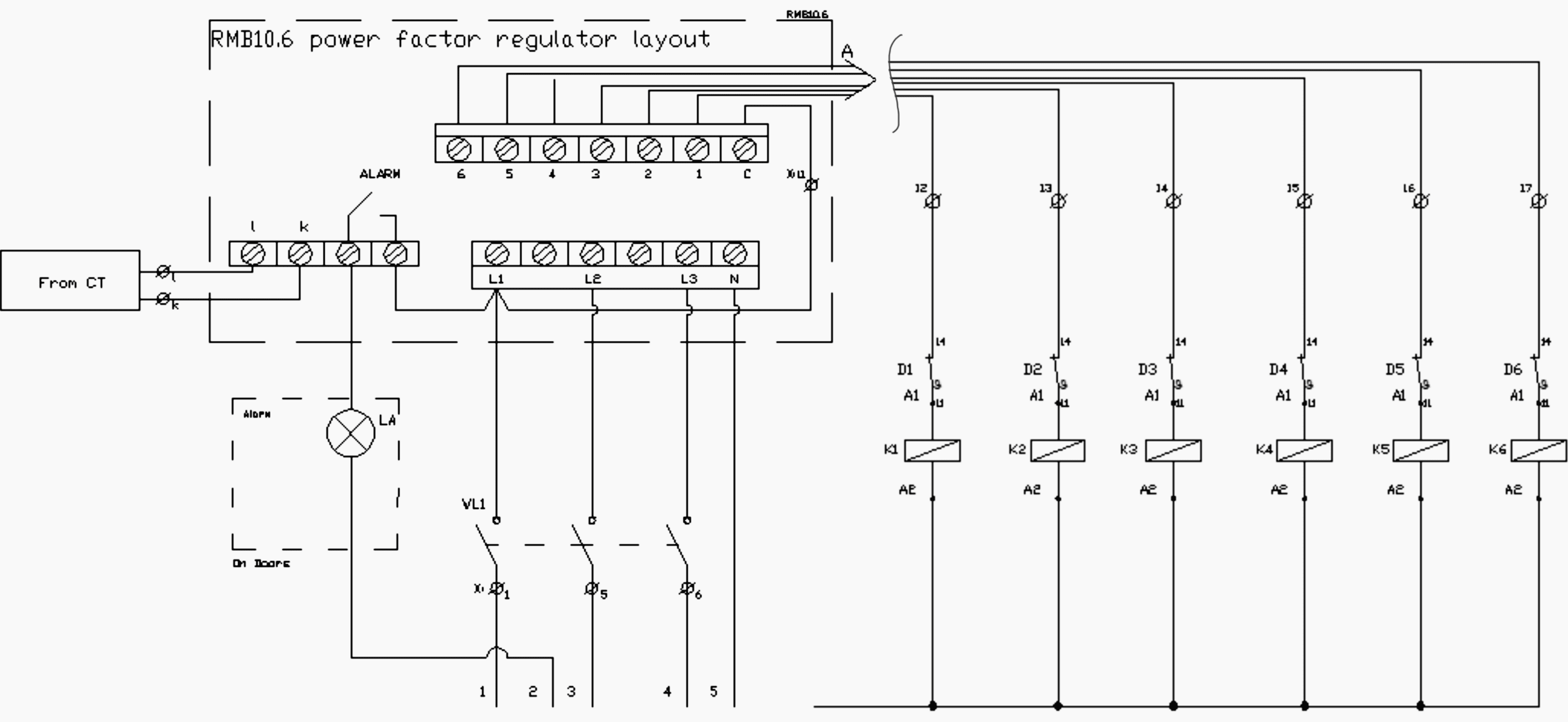
Stepbystep tutorial for building capacitor bank and

Capacitor Bank Control Wiring Diagram

Power Capacitor Bank Wiring Diagram Wiring Diagram
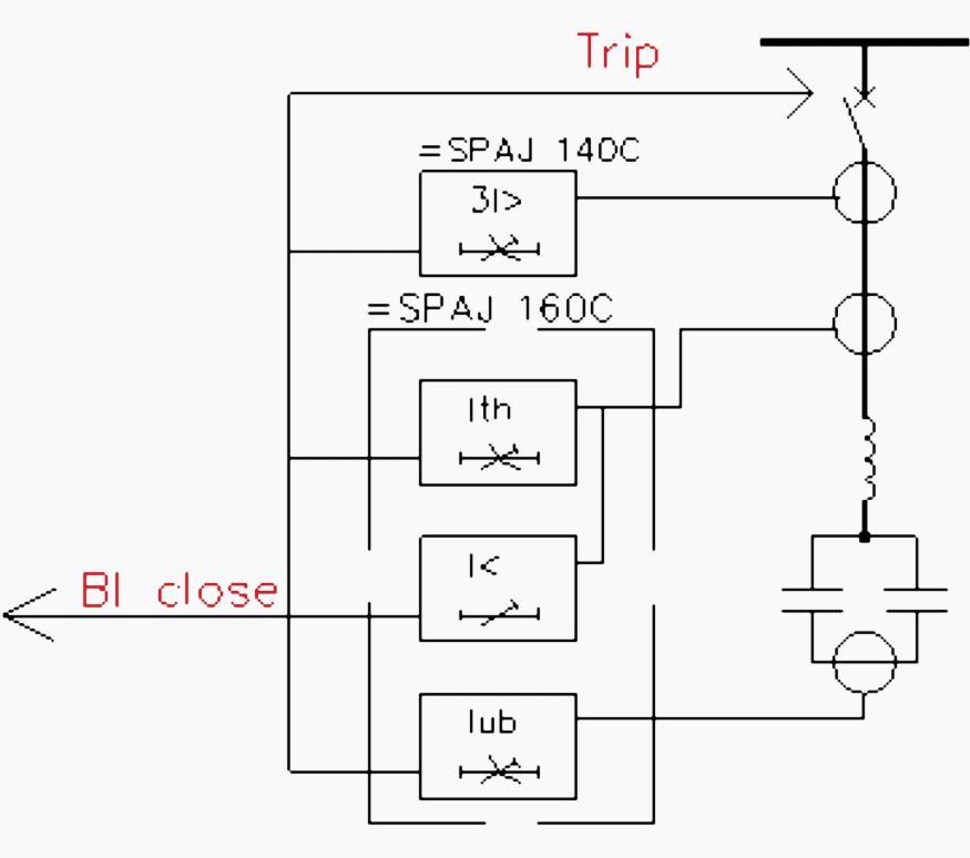
The basics of capacitor banks protection EEP

Capacitor Bank Control Wiring Diagram
Stepbystep tutorial for building capacitor bank and
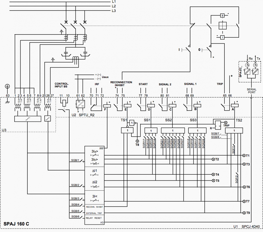
The basics of capacitor banks protection EEP

[ON_9902] Capacitor Bank Wiring Diagram Wiring Diagram

3 Phase Capacitor Bank Wiring Diagram
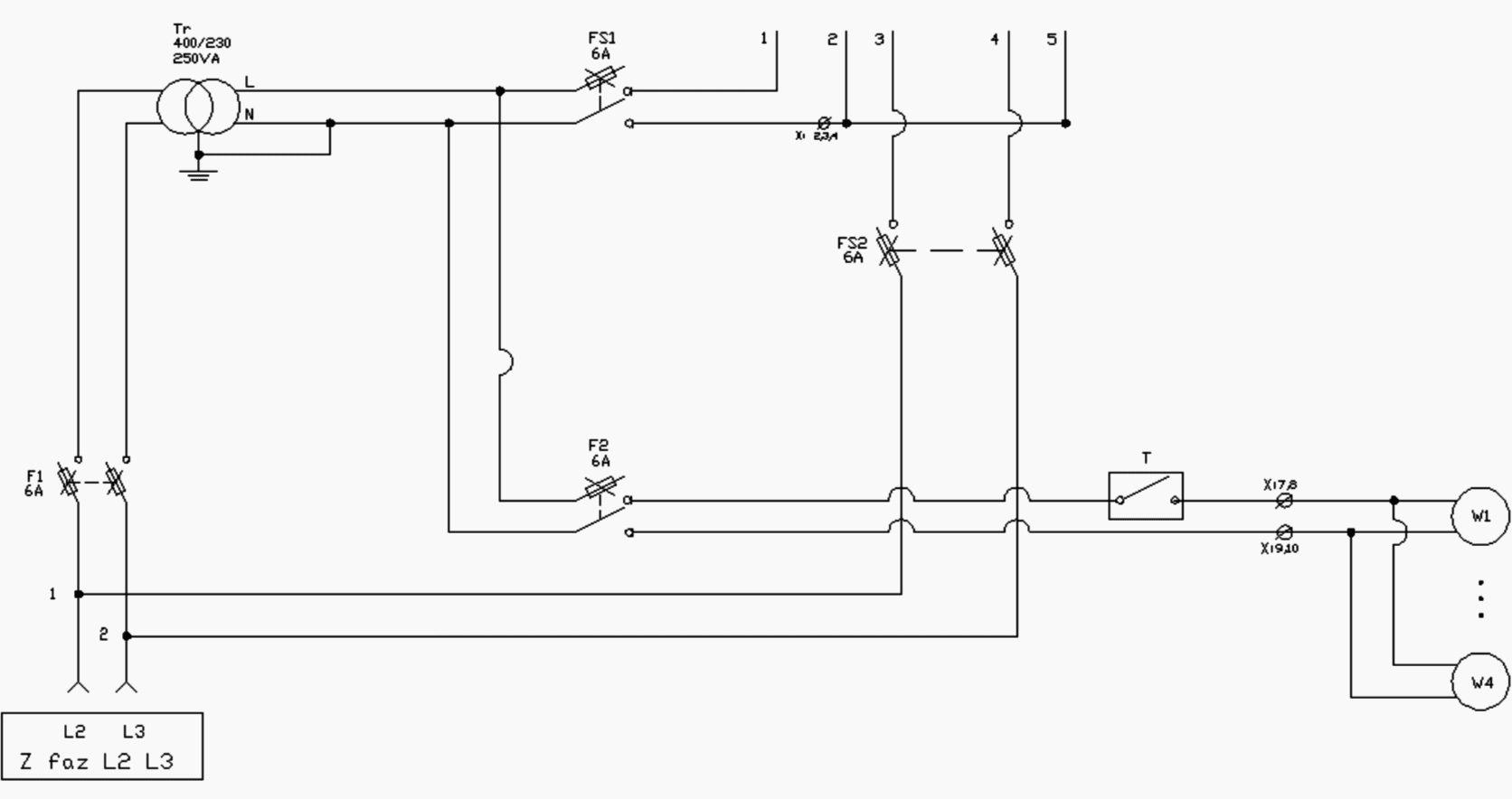
Ac Capacitor Wiring Diagram Cadician's Blog

Wiring Diagram For Capacitor Bank
Tips for power factor correction and good protection of
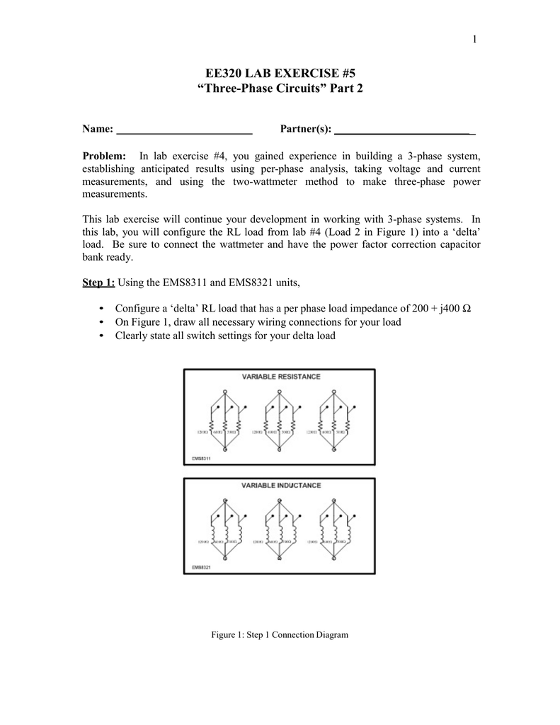
3 Phase Capacitor Bank Wiring Diagram Seputar Bank


