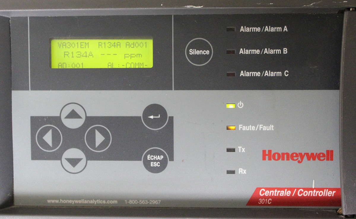
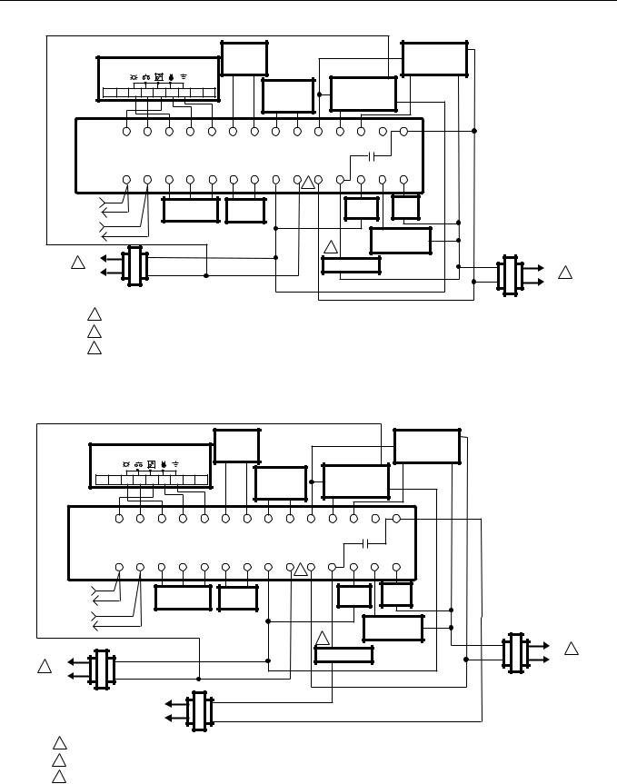
The answer / solution to the problem / question documented in this article. Wiring details the diagram below provides the details required to connect the 301c controller with power, transmitters, external relay loads, and bacnet.

Honeywell Code Encryptor 3 Installation Art guguorlando
Our wiring diagrams section details a selection of key wiring diagrams focused around typical sundial s and y plans.
Honeywell 301c wiring diagram. The answer / solution to the problem / question documented in this article. If you want relay #1 on the 301c. The honeywell 301c controller monitors and controls toxic and combustible gases and oxygen hazards.
Honeywell disclaims all warranties and liability in connection with the drawing. The answer / solution to the problem / question documented in this article. C:userse338647documentsregional sales managerssteven ippolitoha web drawings adi wiring details 301adi (1) author:
301c controller with multiple e3points. If needed scroll to the database menu to delete the programmed event. Honeywell disclaims all warranties and liability in connection with the drawing.
11 (w) x 8 (h) x 2.8 (d) in. The diagram below provides the details required to connect the 301c controller with power, transmitters, external relay loads, and bacnet. Optima plus to the xnx transmitter?
Details concerning power supply, cables, capacities, etc., are provided in the specifications section at the back of. The 301c controller communicates with gas sensors over a modbus. The answer / solution to the problem / question documented in this article.
The honeywell home trademark is used under license from honeywell international inc. Designed for installation and operational efficiency, the 301c reduces the cost of installation and decreases the overall cost of ownership. Zoning can reduce operational costs by ensuring that localized brief fluctuations registered at a single transmitter do not activate relays.
Honeywell home th1110d2009 th1010d2000 thermostat wiring diagrams quality hvac diagram 301c controller with t3 installation how to wire rlv210a owner manual faq combination boiler honeywell home th1110d2009 th1010d2000 th4110u2005 th4210u2002 t4 and t1 pro wiring diagrams user guide manuals thermostat wiring diagrams quality hvac. 201c 301c dip1 dip2 dip3 dip4 1 or 17 81 off off off off 2 or 18 82 on off off off. (r provides a resistance termination and rc
Scroll to the status menu to disables or enable the programmed event. For communication cable, use 24 awg twisted pair, shielded (belden #9841 or equal), cable runs up to 2,000 feet. Designed for simple installation and operation, the 301c continuously monitors and controls toxic gases, combustible gases and oxygen hazards.
Details concerning power supply, cables, capacities, etc., are provided in the specifications section at the back of this manual. Contains all the essential wiring diagrams across our range of heating controls. Sensepoint xcd rfd terminal connections.
Example below has a 2 amp power supply. Designed for simple installation and operation, the 301c continuously monitors and controls toxic gases, combustible gases and oxygen hazards. In this case, you must scroll manually to view screens for other devices.
Modbus communication channels are included. Wiring diagram can be found in the related tab. Code compliance is the sole responsibility of the customer.
Wiring details the diagram below provides the details required to connect the 301c controller with power, transmitters, external relay loads, and bacnet. This knowledge article applies to the following scenario. Honeywell sensepoint xcd transmitters must be configured for 9600 baud, no parity, and a unique address.
The vulcain 301em can be configured to offer automatic fan, horn and strobe activation in addition to manual fan activation. Honeywell warrants to the original purchaser that its product, and the component parts thereof, will. If one or more of the connected devices is in an alarm mode, the controller will only scroll between the main information screen and the screens for device (s) in alarm mode.
301c controller with multiple e3point gas detectors. Select your region and language. How to wire a 301c with an xcd gas detector.
Each e3sm draws approximately 350ma of power. Details concerning power supply, cables, capacities, etc., are provided in the specifications section at the back of. Honeywell home th1110d2009 th1010d2000 thermostat wiring diagrams quality hvac s plan central heating system th8320wf user manual how does an work diagram 301c controller with t6 diynot honeywell home th1110d2009 th1010d2000 th4110u2005 th4210u2002 t4 and t1 pro wiring diagrams user guide manuals thermostat wiring.
Honeywell makes no claim or warranty that the drawing complies with local, state or national building or safety codes. 301c gas detection controllers offer unique zoning capabilities which permit the averaging and comparison of multiple sensor readings. How to wire a 301c with an xcd gas detector.

55 Honeywell Ct410a Wiring Diagram Wiring Diagram Harness

Honeywell Controller 301C with Optional Datalogger and

Honeywell Zone Board Wiring Diagram Wiring Diagram

Honeywell Controller 301C with Optional Datalogger and
E3Point Toxic and Combustible Gas Monitor Fox Valley
OELD Wiring Diagram for Sink or Sourse
55 Honeywell Ct410a Wiring Diagram Wiring Diagram Harness

Honeywell Honeywell Time Clock 301c User's Manual Page
Wiring diagram 301C controller with multiple E3point gas
DC300KE0002000000EN厦门天络纬_工控栏目_机电之家网

55 Honeywell Ct410a Wiring Diagram Wiring Diagram Harness

Central Heating Wiring Diagrams Honeywell Sundial Y Plan

honeywell port air wiring diagramcl25ae Irish Connections
55 Honeywell Ct410a Wiring Diagram Wiring Diagram Harness
55 Honeywell Ct410a Wiring Diagram Wiring Diagram Harness

honeywell port air wiring diagramcl25ae Irish Connections
OELD Wiring Diagram for Sink or Sourse

