
Stinger select radio installation adapter keeps stock a schematic diagram is a picture that represents the components of a process, device, or other object using abstract, often standardized symbols and lines. Ready to take your infotainment experience to the next level?
6 Close the version 3 software and open the new version 4

2 select the file you want to convert and press the open button.

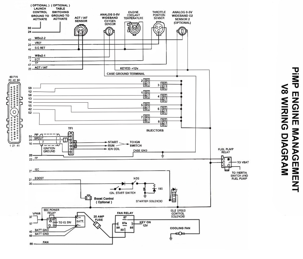
Stinger select sc4rad wiring diagram. Stinger sc4rad wiring diagram, the stinger 4 system provides flexible data logging capabilities to assist in gaining the maximum efficiency from an engine. Wiring harness instructions for stinger 1. Aamp has consistently and continuously bridged barriers that separate you and your car from new technology.
Small red wire connects to. Yay time for me to butt in. Get excited, because your ride is about to get a lot more exciting with your new elev8 or heigh10®.
Diagram kia stinger wiring diagram full version hd quality. 1 select the open tune files option and then select stinger 3 tune files in the file of type field. 3ea 14 gauge (large) green wire connects to battery positive + (30amp fuse for each wire) 2.
Diode 1 striped side goes to green wire of prox sensor. Ems stinger wiring diagram gallery of volvo ems2 wiring diagram download credit: The sc4rad interface allows the retention of steering wheel controls when replacing a factory radio in a vehicle equipped with analog steering wheel controls.
Wiring schematic diagram free download unique steering wheel radio. Additionally, you can use the swc toolbox to find a bunch of helpful information, including programming instructions, wiring diagrams and a swc resistance calculator. The color scheme is generally standard for vehicles of every yea the general motors gm radio wire harness uses gray, orange, yellow, pink and black c.
Steering wheel control input adapter. Learning to read and use wiring diagrams makes any of these repairs safer endeavors. I need a schematic for a circuit using a 555 timer.
Once saved, the file will be converted to version 4. To change to the next program,. (this will show all stinger 3 tune files).
Stinger electronics we design and engineer technology that makes your drive more fun. Highly visible led to keep the user informed of the modules status. Professional installation is recommended for any of.
For warranty information, view our pac warranty page. All version 2 files must be converted to version 3 first. Pac is a brand of aamp global.
Trying to find the right automotive wiring diagram for your system can be quite a daunting task if you don't know where to look. Stinger hardware installation guide part number: Built for audiophiles by audiophiles our products span infotainment and radio upgrades, audio upgrades and all the installation accessories to make those enhancements easy.
Update via the sc4rad pc application. Diode 2 striped side goes to blue. Old, new, commercial, passenger, foreign or domestic, we give you the freedom to enhance the vehicle you love with the features you crave.
Stinger has everything a true audiophile, and passionate accessorizer needs to upgrade a vehicle's sound or infotainment system, or upfit your boat, sxs, or car with the latest accessories. If you want to hook up a prox sensor to the alarm you can hook both the green and blue wires to that extra green wire from the shock sensor harness just make sure you use diodes on each of the wires coming from the prox sensor. For fans of movies where things explode and people get kicked in the face.
Available in power and complete (power + signal) kits, stinger’s wiring kits have all the essentials for a professional installation. These radios’ swc wires are often identified as key 1 and key 2, or sw 1 and sw 2. Steering wheel control input adapter for 2 wire resistive radios.
Stinger has everything a true audiophile, and passionate accessorizer needs to upgrade a vehicle's sound or infotainment system, or upfit your boat, sxs, or car with the latest accessories. 12 gauge (large) black wire connects to negative battery terminal (do not bolt this wire to chassis) 3. Once the voltmeter reads 12 volts or close to it you can remove the voltmeter and replace the resistor with the power fuse.
Stinger sc4rad wiring diagram, the stinger 4 system provides flexible data logging capabilities to assist in gaining the maximum efficiency from an engine. The swi's use the same 4 wires for these circuits. Located just outside of chicago illinois.

Farad Capacitor Wiring Diagram

STINGER SELECT SC4RAD Universal Steering Wheel Control radio

Wiring Diagram Of Capacitor For Car Wiring Diagram Schemas

Bha 17j11suba Wiring Diagram
PM65 and XS questions Stinger Performance Engineering

KIA Stinger (2018+) Head Unit pinout diagram
6 Close the version 3 software and open the new version 4

Stinger 1 Farad Capacitor Manual Electronic Diagram

2 Channel Line Output Converter Installation
53 Ssgm31 Wiring Diagram Wiring Diagram Plan

53 Ssgm31 Wiring Diagram Wiring Diagram Plan
Stinger Capacitor Wiring Diagram

Stinger Select SSPRCA1.5 Performance Series 1.5 Coaxial

Stinger Select SSPRCA1.5 Performance Series 1.5 Coaxial

Stinger Select SSPRCA1.5 Performance Series 1.5 Coaxial

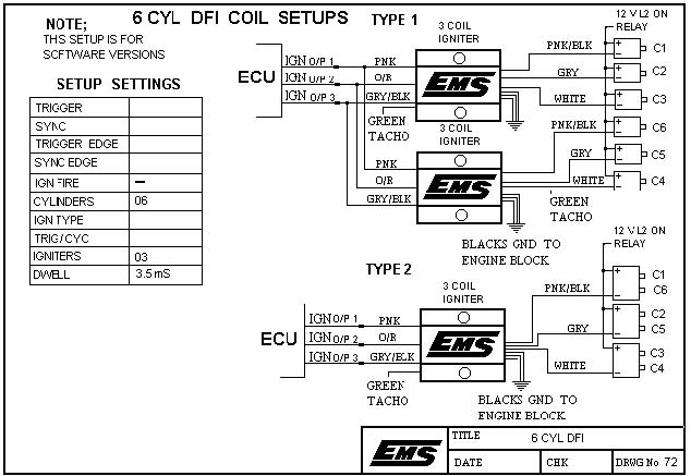
Ems Stinger Wiring Diagram
255 lph or Larger Fuel Pump Wiring Diagram Stinger


STINGER SELECT SC4RAD Universal Steering Wheel Control radio

Select Line Output Converters Stinger Electronics