
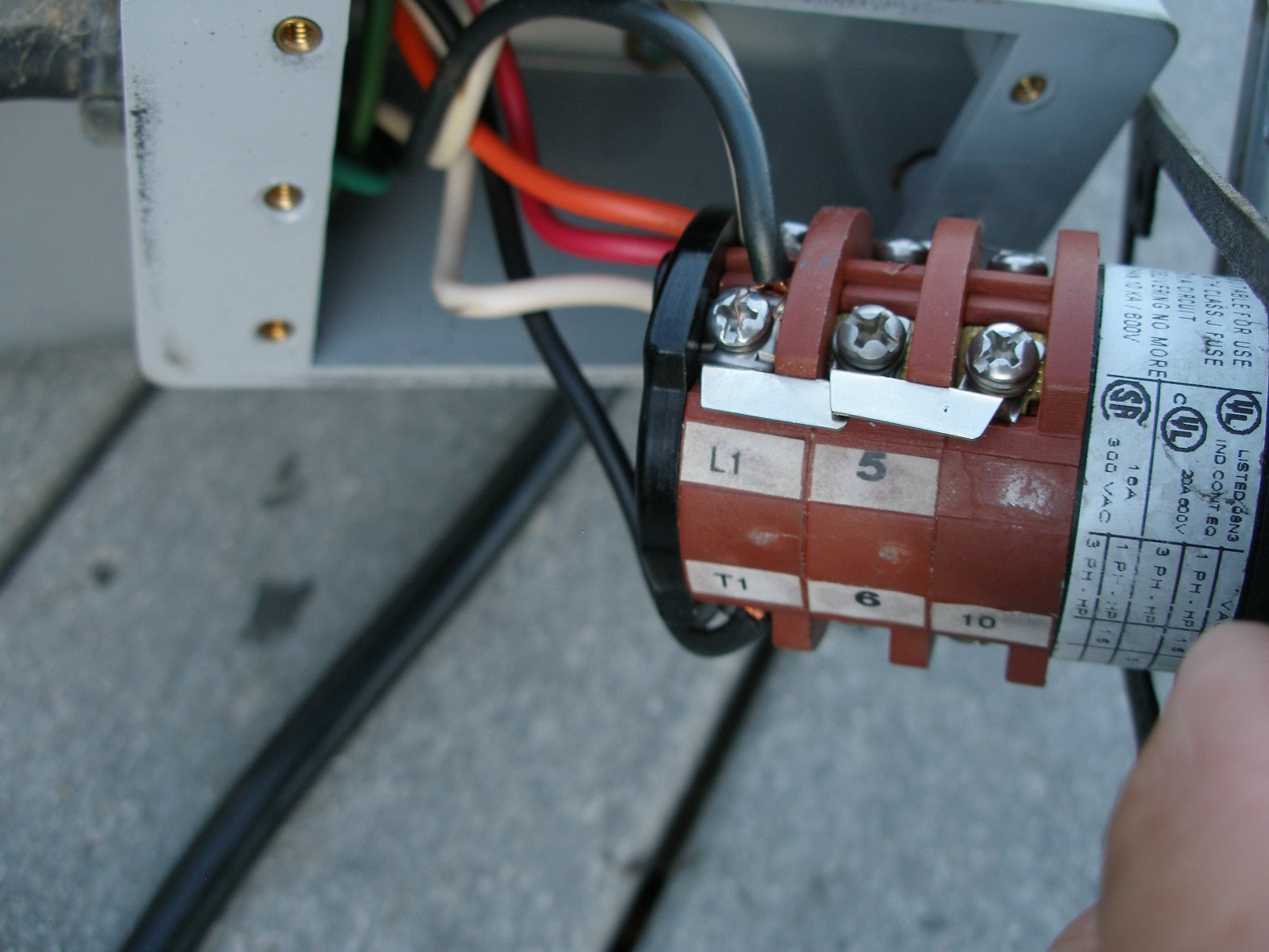
The bremas momentary boat lift switch requires the user to hold the handle in place to lift or lower the boat. 2 strands per line (1 strand is black with white markings (assuming positive), 1 strand is solid black (assuming ground).
I have a GHA Bremas switch for a boat lift. the motor is
8kw off grid solar system.
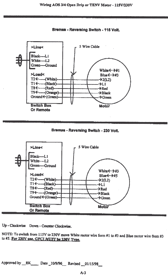
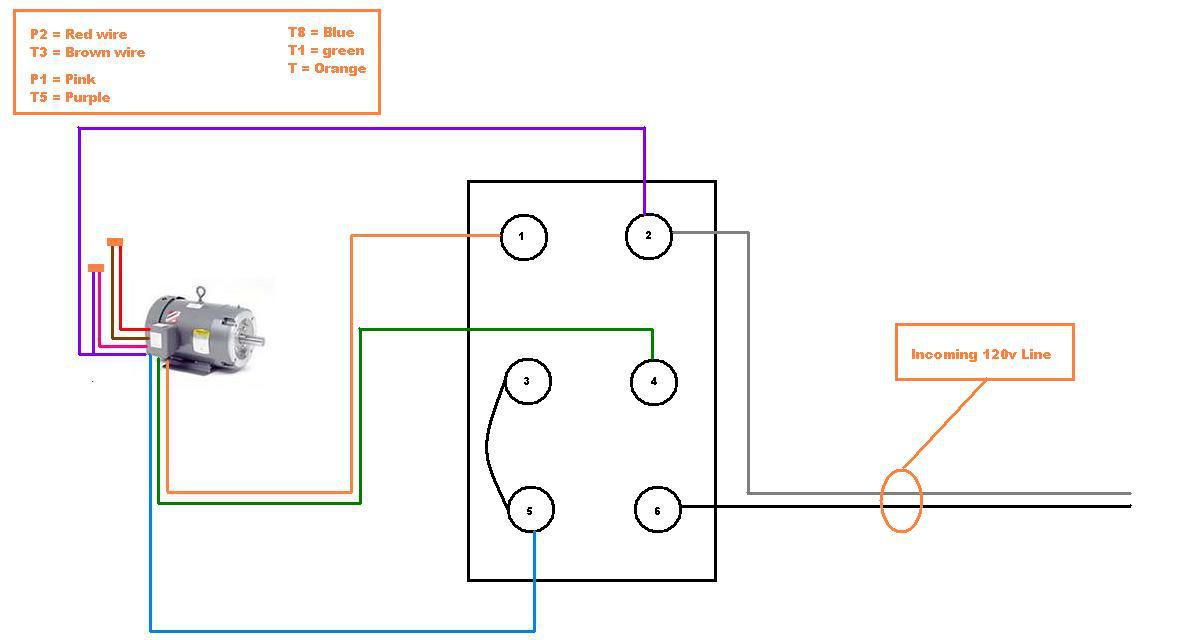
Bremas switch wiring diagram. Bremas drum switch wiring diagram. Connect motor black wire to switch red wire with wire nut connect orange wire to motor terminal 2. To switch from 115v to 230v move white motor wire form #1 to #3 and blue motor wire from #3 to #5, wire nut the motor black to the motor orange & put wire nut orange from switch.
A wiring diagram generally gives details about the loved… Bremas boat lift switch wiring diagram. Variety of bremas boat lift switch wiring diagram.
Wiring diagram of single phase kwh meter bremas switch wiring in solar net metering wiring diagram image size 914 x 459 px and to view image details please click the. This bremas boat lift motor switch (drum switch) is found on most boat lifts and comes as a maintain switch. Features durable molded plastic housing and gasket sealed box.
It shows the elements of the circuit as streamlined shapes, and the power and also signal connections between the tools. When wiring at 120 vac Dayton drum switch wiring diagram for bremas reversible reversing motors with a forward reverse practical machinist largest qs60 light 110v full need assistance on electrician talk single phase motor switching of bremis boat lift 120v split 2 hp electric switches doityourself com question eeweb i am trying to wire 110 volt ac capacitor qs 60 3.
Connect motor #1 wires to lugs on bottom right side of the contactor as labeled: Replacing your boat lift drum switches with the same mfg will make the process easier for you. These switches enable you to control one or more fixtures from.
Bremas america is focused on marketing, promoting and supplying the bremas and ercse brand product lines. For 230v use, gfci must be 230v type. When replacing boat lift motor switches always check your connections and the condition of the wire.
Please click a product category to browse the products within it. Equipment guide rvsd this is intended for the end. Bremas boat lift switch wiring diagram elegant bremas drum switch sample.
Catalogue 2010 7 circuit diagrams switches plate scheme cirfunction contact/element descriptioncuit diagram element no. The bremas maintained boat lift switch stays in position until it is manually turned off. Bremas momentary boat lift switch.
Bremas boat lift switch wiring diagram. Please double check the switch wiring to ensure the wires are connected in the correct place using the switch wiring diagram on page 6. The lock on switch features durable molded plastic housing and gasket.
A wiring diagram is a streamlined standard photographic depiction of an electric circuit. Bremas # cy0178099s2r, bremas # cy0178068s2r, furnas # d74756002, furnas # 057341002 leeson motors and electra gear 115vac wiring procedure for 3/4 hp leeson motor # c4c17nh11b, 1 hp leeson # c4c17nh12b and 1.5 hp leeson motor 21 images bremas drum switch wiring diagram 2018 08 23t171400 0700 rating.
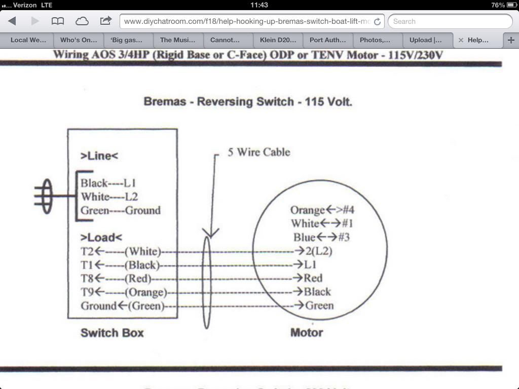
To switch from 115v to 230v move white motor wire from #1 to #3 and blue motor wire from #3 to #5, put a flag on the black motor wire then hook to post #4, put wire nut on orange wire from switch (not used). Power at light wiring diagram wiring diagram collection. With over 50 years of experience, bremas is a specialist in the industrial sector for standard and custom products.
Ul, nema, ce, sa compliant. Available diagrams for every application: This bremas boatlift motor drum switch is found on most boatlifts and comes as a if you need a wiring diagram to install your boat lift motor to any of our boat.
Bremas is a leader in the design, manufacturing and marketing of cam switches, switch disconnectors, position and safety switches, push buttons, relay sockets and power tools switches. The following procedure is for wiring the already wired drum switch* to the motor using 14/5 bremas # cys2r, bremas # cys2r, furnas. Motor #1 red(top), m#1 black(middle), m#1 orange(bottom).
Click here to see other images of bremas switch wiring diagram. A wiring diagram is a simplified traditional pictorial representation of an electrical circuit. The following procedure is for wiring the already wired drum switch* to the motor using 14/5 bremas # cys2r, bremas # cys2r, furnas.
A wiring diagram is a type of schematic which uses abstract photographic icons to show all the affiliations of components in a system. Ams reversing switch use the below diagrams if your control is an aqua marine supply reversing switch.

Bremas Boat Lift Switch Wiring Diagram Free Diagram For

reversing drum switch wiring diagram Wiring Diagram
35 Bremas Switch Wiring Diagram Worksheet Cloud


Bremas Switch Lunmar Boat Lifts

Bremas Boat Lift Switch Wiring Diagram Sample
Bremas Boat Lift Switch Wiring Diagram
1E1F58 Bremas Drum Switch Wiring Diagram Ebook Databases
34 Bremas Boat Lift Switch Wiring Diagram Wiring Diagram

Bremas Boat Lift Switch Wiring Diagram Sample

Bremas Boat Lift Switch Wiring Diagram

Bremas Reversing Switch Wiring Diagram

Bremas Boat Lift Switch Wiring Diagram Free Wiring Diagram
Bremas Boat Lift Switch Wiring Diagram

Bremas Boat Lift Switch Wiring Diagram Collection
Bremas Reversing Switch Wiring Diagram

Bremas Boat Lift Switch Wiring Diagram

Bremas Boat Lift Switch Wiring Diagram Free Wiring Diagram
Bremas Switch Wiring Diagram Wiring Diagram

Bremas Boat Lift Switch Wiring Diagram Free Wiring Diagram