Gm 3800 ignition wiring diagram. 5617614 ford ignition control module wiring diagram.
1997 Ford F350 Ignition Wiring Diagram Wiring Diagram
Locate the johnson controls part number on the existing module.

3800 ignition control module wiring diagram. Ignition system circuit diagram 1998 3 wiring 1995 gm 8l vin 3800 c engines code part control module coil icm test forum buick cadillac fuel injector 89 park avenue to series belt er motor 1996 1999 firing order i was at a diagnostic servicing s v6 diagnose engine all diagrams for lacrosse problem. It contains directions and diagrams for different types of wiring methods as well as other things like lights, windows, etc. With the red multimeter test lead and a wire piercing probe, probe the pink wire of the connector shown in the figure above.
Push the square cut fover the pcm attachment nut. By continuing to use this site you consent to the use of cookies on your device as described in our cookie policy unless you have disabled them. It was a copy i had to photoshop to make it readable & printable.
The complaint is the engine cranks normally, but does not start. If no, go to step #3. Over the years johnson controls has gone through many different model variations.
The correction for this issue becomes the replacement of the failed component. Ignition control module wiring help!!!!. Q347 spark ignitor & ignition cable q354 flame sensor procedure 1.
Q instructor approves setup and wiring. All fuses and fuse links have been checked. Buick 3800 engine problem diagnostics autointhebox.
Does anyone have a schematic diagram for the bosch ignition control module? If the pilot assembly starts sparking, replace wire harness. The crankshaft position sensor and the ignition module have already been replaced.
Vw ignition control module diagram. Associated wiring diagrams for the cruise control system of a 1990 honda civic. The cause of an ignition control module failure is often associated with age and damage from heat buildup.
Before starting the tests you must first check and verify that there's no spark present at any of the coil towers. Each component ought to be set and connected with different parts in specific way. The module comes off of other gm vehicles.
Refer to wiring diagram number existing module (control part) part number 3. 6 dk grn low speed fan control connect to d1 of fiero c500 connector; I've already made up an alternative that's very affordable that will fit inside the bosch control box and uses half.
Through the lower front hole of the pcm shield and then through the side hold of the pcm cover. The crank sensor contains two hall effect sensors that sends two signals to the engine computer. Use jumper wires to connect the components.
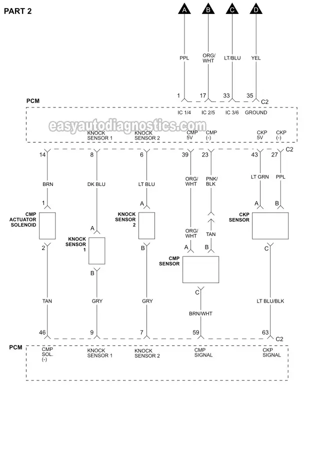
Should be dk grn/wht wire 7 blk cam position input connect to f of ignition control module harness (also pin f of icm) 8 ppl/wht 3x reference signal (low res / fuel control) connect to d of ignition control module harness (also pin d of icm) I've been running this setup for years at 25+ psi with ngk yr5 plugs with zero issues. Q refer to the wiring diagram and pictures on the next page.
With the key on, you should find about 4 to 8 volts between each of the crank sensors two output circuits and the low voltage reference circuit. Lt1 ignition control module wiring diagram. It has a no spark condition, it does have injector pulse and fuel pressure.
Q locate the components needed for this lab and mount them on the trainer. In 1995, the 3800 series ii v6 engine joined the 3. I use the type ii ignition that uses the 3800 series ii type coils which work great and are plentiful.
Diagnosing the crank sensor requires looking up the engine wiring diagram for your vehicle, then testing the voltages for the various crank sensor and ignition module circuits to find the fault. I believe the thing i need is a wiring diagram for a 1998 olds 88 3800 series. Chevrolet 1500 wt truck how do you install 4 3 distributor, chevythunder, gm gen iii ls pcm ecm how to change the firing order ls, 3800 v6 engine sensor locations pictures and diagrams , silveradosierra com free online wiring diagrams , silveradosierra com roof top wiring harness electrical, the best and completed full edition of diagram database website you can.
There are a variety of possible causes for a no start, but one of the most common with the 3800 engine is a bad crankshaft position (ckp) sensor or a bad ignition control module (icm). Cabinet construction is similar to the packaged rooftop units with easily accessible coil connections. Wiring diagram includes several in depth illustrations that display the connection of varied items.
If not, the structure won’t function as it ought to be. 86 302 ignition control module wiring diagram. Sep 12, 2019 #2 this is very old technology.
I'd like to see how bosch does the interface to the reluctor coil. Disconnect the ignition control module (icm) from its connector. Ignition module failure is no joke because it often leaves you stranded.
Remove the horn wiring attachment clip and reinstall through the shield. Ford ignition control module wiring diagram. It's just another option if you don't want to fork the money for tr6.
Gm 3.8l ignition control module and crank (3x, 18x) sensor test. Tpi ignition control module wiring diagram. This is the wire labeled with the letter p in the illustration above.
Revtech Ignition Module Wiring Diagram
1997 Ford F350 Ignition Wiring Diagram Wiring Diagram
ford f350 wiring diagram free Wiring Diagram and Schematics


Ignition Module Wiring Diagram Mazda Ignition Control

How To Bypass Ignition Switch On Car All information
I have a 96 Chevy blazer with a small cap hei distributor

Harley Ignition Switch Wiring Diagram Wiring Diagram
Help with ignition wiring!!! Ford Truck Enthusiasts Forums
I have a 1995 Buick Regal Custom 3800 v6 with about

Audi Wiring Diagrams Free Download

Where is a esc module on a 95 buick park ave. 3800 series

Ignition Coil Wiring Diagram Ford / Ford Electronic
2011 Chevy Malibu Wiring Diagram Wiring Diagram
electronic ignition wiring diagrams Wiring Diagram and
In my 1994 olds 98 i keep getting code P0341, and P0342
Ford Ignition Module Wiring Diagram / Ignition control
Electrical expert needed. i have a wiring problem on my taurus


41 points and condenser wiring diagram Wiring Diagram

2004 Jeep Grand Cherokee Starter Wiring Diagram inspire