
What you have to do is make the brake light wires and the turn signal wires combine in a way that the turn signal wires can override the brake signal. It’s not physical circuits that are joined together somewhere.
How to Add Turn Signals and Wire Them Up
Which are separate from the brake lights.
Combined brake and turn signal wiring diagram. Hard wire only vehicle has combined brake and turn signals brake light wire on harness is not grounded. Combined brake and turn signal wiring diagram. The wire from the brake light switch (should be white) needs to be wired into the turn signal switch instead of going directly to the brake lights.
If your stop and turn wires are combined, meaning that they travel down the same wire, then you will only need one taillight on each side. Thats why there are numerous. The front bulbs must be switched seperatly from the rear.
2 speeds 1 direction 3 phase motor power and control diagrams electrical circuit diagram electrical engineering quotes basic electrical wiring. E d f a1 a Roadmaster has wiring diagrams on their web site that cover various toad wiring configurations.
At this point run your wires to the rear lights. See diagram b2 for later wiring diagram. This listing is for 2 sockets does not include relay relays and sockets are used for many car electronic applications to turn on/off almost any device.
The vehicle will be wired for towing according to the type of brake and turn signals in both vehicles. If your stop and turn wires are separated, you will need to two taillights on each side: Yes, i will attach a snip of the installation as well as post it here.
On the output side you will have the yellow wire for left turn signal only, green for right turn signal only, and red for brake lights only. Up to ts12567, july, 1955. Welcome to another garageless video.enjoy, like, comment and subscribe.deathtrap fiero build:my custom louversmy custom quarter panels3400 la1 comp 26918.
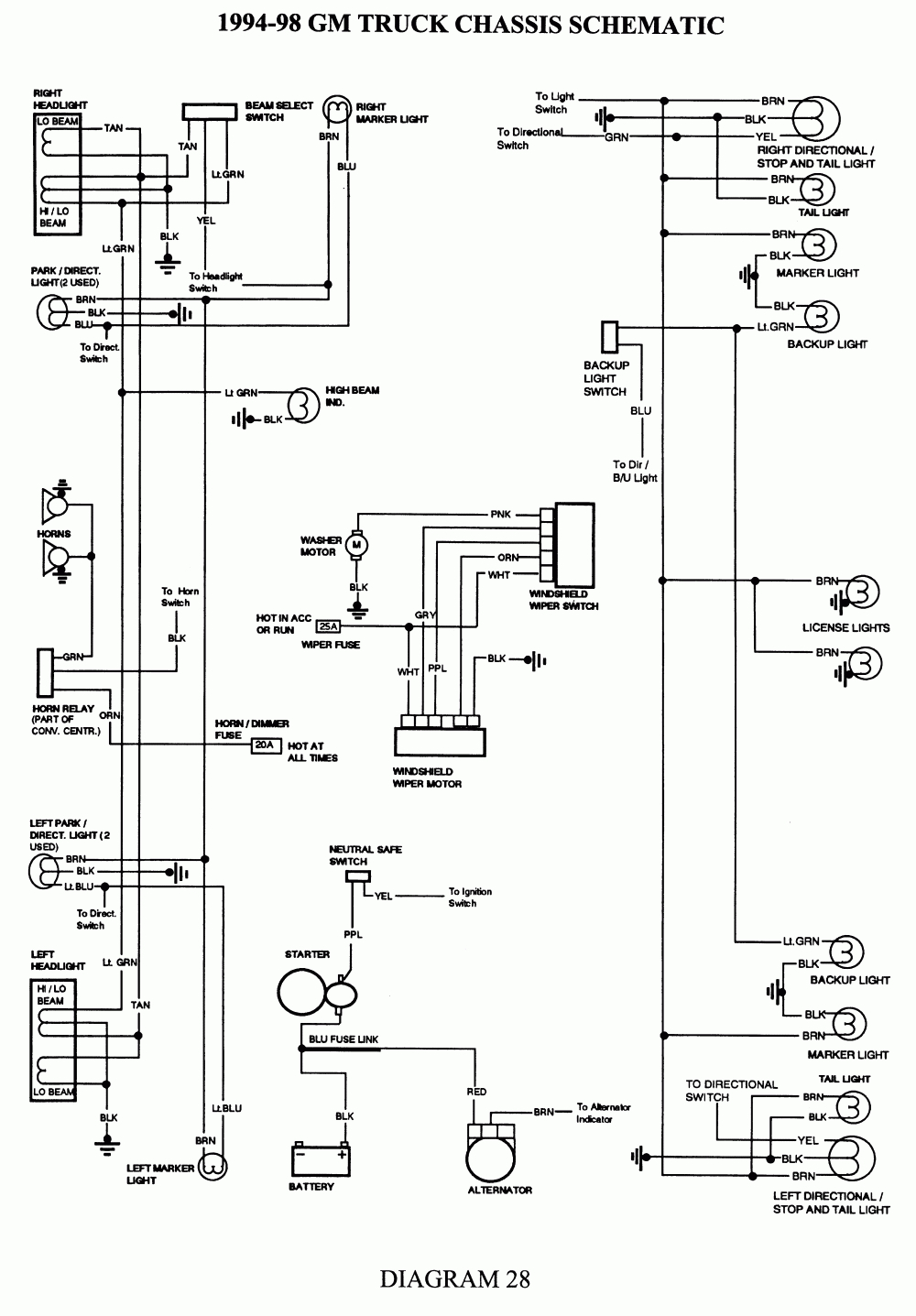
A circuit is generally composed by several components. Here is a simple gm turn signal wiring diagram that might help: L turn/brake , r turn/brake, tail lights, ground.
If the towed vehicle’s brake lights override the turn signal… Some have the tail light wire running through them 4 wire into 3 wire and some dont 3 wire into 2 wire. A circuit is generally composed by several components.
From the turn signal switch, a yellow wire should go to the left turn/stop lamp, and a green wire should go to the right turn/stop lamp. Curt makes a module designed to separate the circuits for trailer lighting. In a combined system (figure 1), the brake light flashes for the turn signal;
Only one switch fitted prior to this change. Combined brake and turn signal wiring diagram from fiddlingwithzcars.files.wordpress.com print the wiring diagram off plus use highlighters to trace the signal. If you are using independent rear turning signal lights just connect the rear wires to the terminals with the front signal lights (2 and 4) in the wiring diagram and eliminate 1,3, and 5 and run the wire to the single brake light through the brake light switch.
The switching consists of (2) dpdt switches (double pole double throw, maintained). When you make use of your finger or perhaps the actual circuit with your eyes, it is easy to mistrace the circuit. Od was operative only in top up to ts6266, may, 1955.
At this point you can't run the wires to the front. Battery to ignition switch and turn signal relay with tail brake lamp wiring diagram motorcycle wiring electrical wiring diagram electrical diagram It was not common in those days and took some work to get it all to work correctly.
Simply omit them if not needed. Best wiring diagram polaris e bike for controller electric bike diy electric bike razor electric scooter. Connect yellow wire (input) to towing vehicle’s left turn/brake wire.
1 trick that we 2 to printing a similar wiring plan off twice. There are two types — combined or separate. Runs your wires into the converter and coming out of the converter will be four wires.
Now they have small boxes that you can add in to handle the conversion. There are complicated ways to wire in multiple relays to do it, and aftermarket units that will do this but there is an easier way. The white input wire is ground (earth), yellow is combined left turn signal and brake light, and green is combined right turn and brake light.
A quick and cheap way that works just as good is a tail light wiring converter for trailers. Porsche cayenne tail light wiring diagram stop brake light rear turn signal light bulb reverse. The diodes are for isolating parts of the car circuitry from a tow vehicle.
One brake light fitted up to ts15601, may, 1957, for us market. Ac condenser fan motor wiring diagram 4 wire beautiful for new 7 fan motor ceiling fan wiring electrical. 5 way trailer wiring diagram allows basic hookup of the trailer and allows using 3 main lighting functions and 1 extra function.
Separate stop and turn wires. Green right turn signal right brake light. Combined brake and turn signal lights — the brake light does the flashing for the turn signal.
The attached schematic shows typical turn signal switching when a dual filament bulb is used for brakes and turn signals. They are also used when a device draws heavy amperage such as car alarms, remote starts, fog lights, stereos, fans, hid. What is it you’re trying to do?
Sep ara te brake and turn signal lights — there are amber or red turn signals1. Years ago, the biggest problem i had wiring a chev c60 to pull boat trailer was the truck had separate turn signal wires (not combined with brake lights). Connect green wire (input) to towing vehicle’s right turn/brake wire.
Since the turn signal uses the same filament as. 4 wire tail light wiring diagram wiring diagram is a simplified up to standard pictorial representation of an electrical circuit. In a 1 separate system (figure 1), there are amber or red turn signal lights which are separate from the brake lights.
Brake light and turn signal wiring diagram.
Best Harley tail light turn signal combination (2021 Top

Installing Turn Signals Electricity, Electrical wiring
Wiring Tail Lights And Turn Signals Wiring Diagram
Diy Led Turn Signal Resistor

Standalone Blinkers/brake lights help Miata Turbo Forum
1978 Z28 Turn Signal/Brake Light/Hazard Issue Page 2

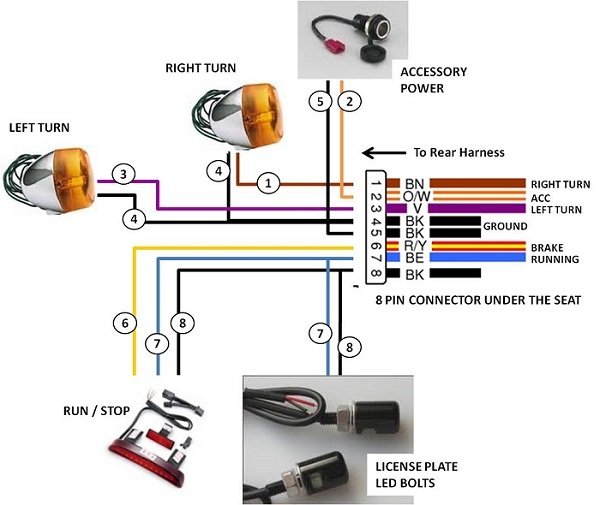
How to Wire a Motorcycle (Basic Wiring Diagrams
29 How To Wire Turn Signals On A Motorcycle Diagram

Brake Lights Wiring Diagram Wiring Diagram
Grote Turn Signal Switch Wiring Diagram

Brake And Turn Signal Wiring Diagram Wiring Diagram
Beetle OvalWindow 195357 View
Turn Signal Wiring Diagram Jrlovvorn Flickr

Universal Turn Signal Switch Wiring Diagram Fitfathers Me
Brake And Turn Signal Wiring Diagram Wiring Diagram
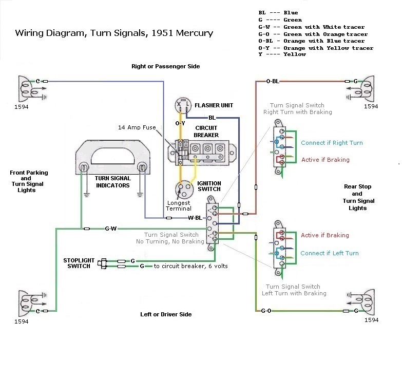
1951 Mercury, an American Legacy

Technical 51 3100 no brake lights, added turn signal
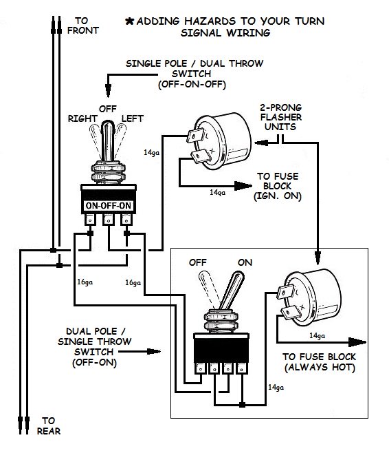
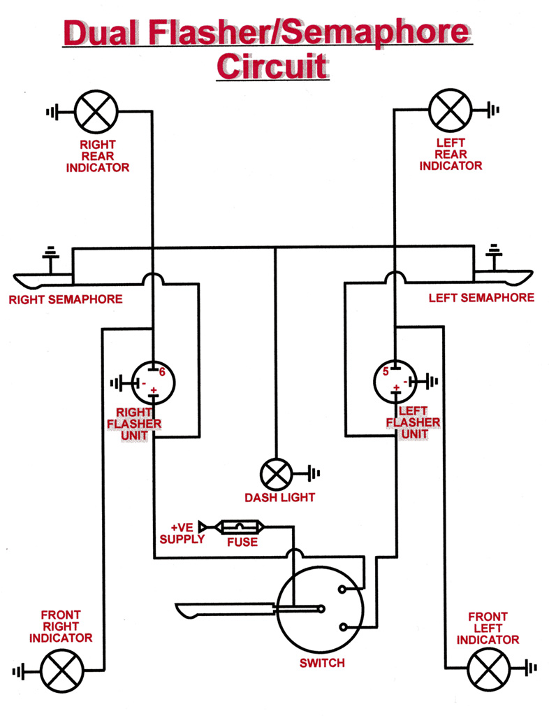
Flashers and Hazards

The Care and Feeding of Ponies 1965 1966 Mustang Turn