
Another wire only shows (+) 12v dc during lock and ground at rest. The correct wire for the power unlock is purple w/green stripe.
What is the wiring code for the power door lock switches
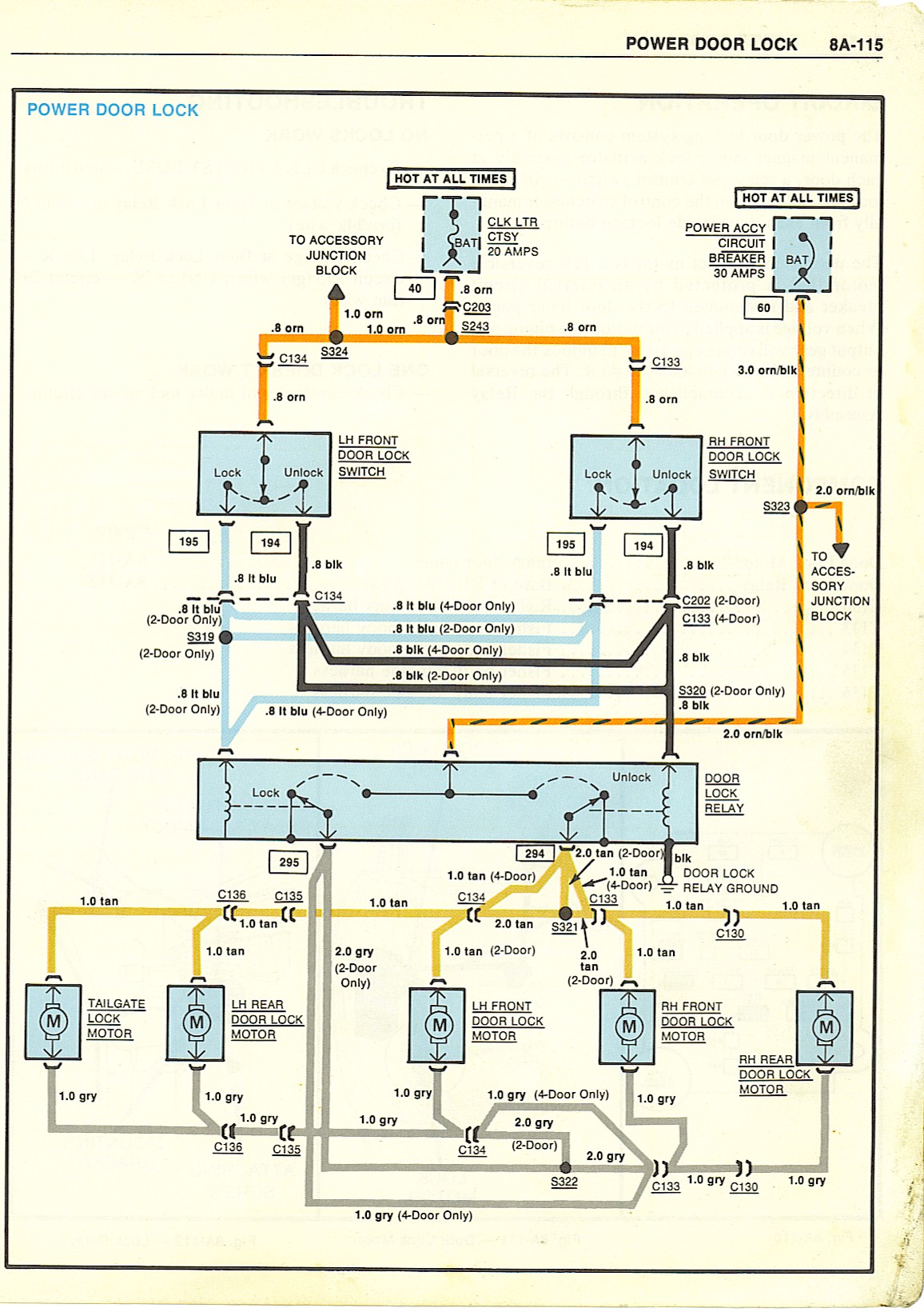
When the switch is not being pressed in either direction then the black and light blue wire will be in a disconnected state.

Power door lock wiring diagram. If you look closely you. I have a 94 camaro that i install power windows and locks from a 99 firebird. 3 wire positive door locks (type a) there are three wires in the harness not counting the illumination wire(s), if any.
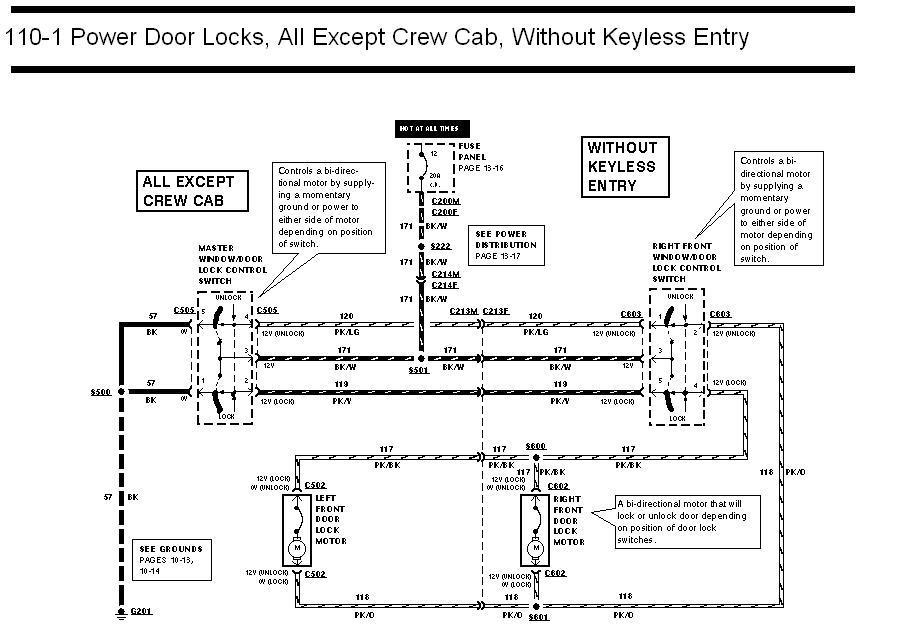
Disconnect left front door lock actuator. 6 (pink/black wire) and left front door lock actuator harness connector circuit no. 1 trick that we 2 to printing a similar wiring plan off twice.
I ran the wire under the carpet to the door threshold into the wire tray and up to the b pillar and spliced it close to the plug connection for the rear door. Reminder system, keyless/power door lock system blu/red 61blu/redwithout super locking: The last wire only shows (+) 12v dc during unlock and ground at rest.
Does anyone have a wiring diagram so i know what wires to check with the dvom? If resistance is less than 5 ohms, go to next step. There is a dedicated lock power supply and a separate power supply for the controller.
You will only need common hand tools for the repair but i would recommend that you have a wiring diagram and shop manual available for your year corvette. In some instances a weak door lock actuator may still be able to operate the door lock but operation may be sluggish andor intermittent. How to wire power door lock actuators and power window kits.
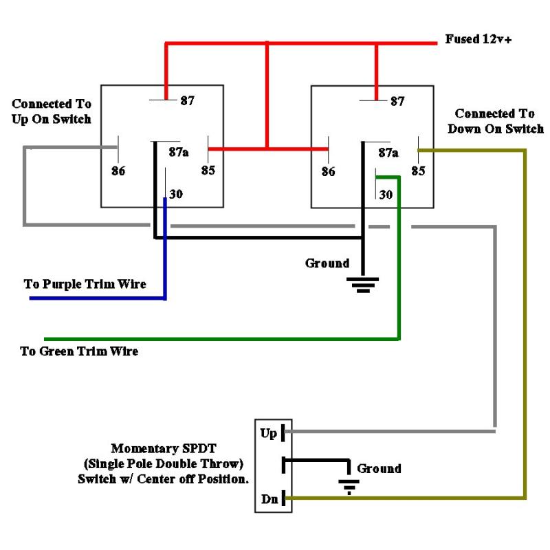
Now let’s get to work and put the switch on. Joined aug 16, 2005 · 2 posts. The pole of the switch should connect to ground and the other two terminals of the switch should independently connect to pins 85 and 86 of each relay.
From www.justanswer.com a wiring diagram or schematic… Ensure right power door lock switch is disconnected. With entry light control system grn/red48 power door lock control circuit 5025beeper cpu g401lt grn/red wht/blk yelwht g401 whtgrn blk g401 g401wht g401 yel wht/blkrelay holderdrive circuit blk blk blk blk.
With this sort of an illustrative manual, you will have the ability to troubleshoot, avoid, and total your tasks without difficulty. The door looks in my brothers 06 supercrew doesn't work with either switch or the key fob. What is the wiring code for the power door lock switches.
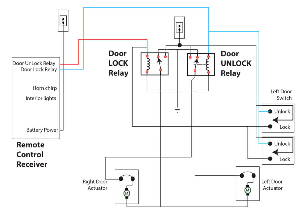
The tan and gray wire pairs in each door are the door lock motors (actuators). If your alarm or keyless entry has positive outputs only, you will have to connect the other side of the coils to ground and connect your outputs as shown. Power door lock actuator wiring diagram.
Should you need to add relays for a 3 wire negative (type b) door lock system, use the diagram below. Here s a power door lock wiring diagram for a 2009 chevrolet malibu. Power door lock positive wire location:
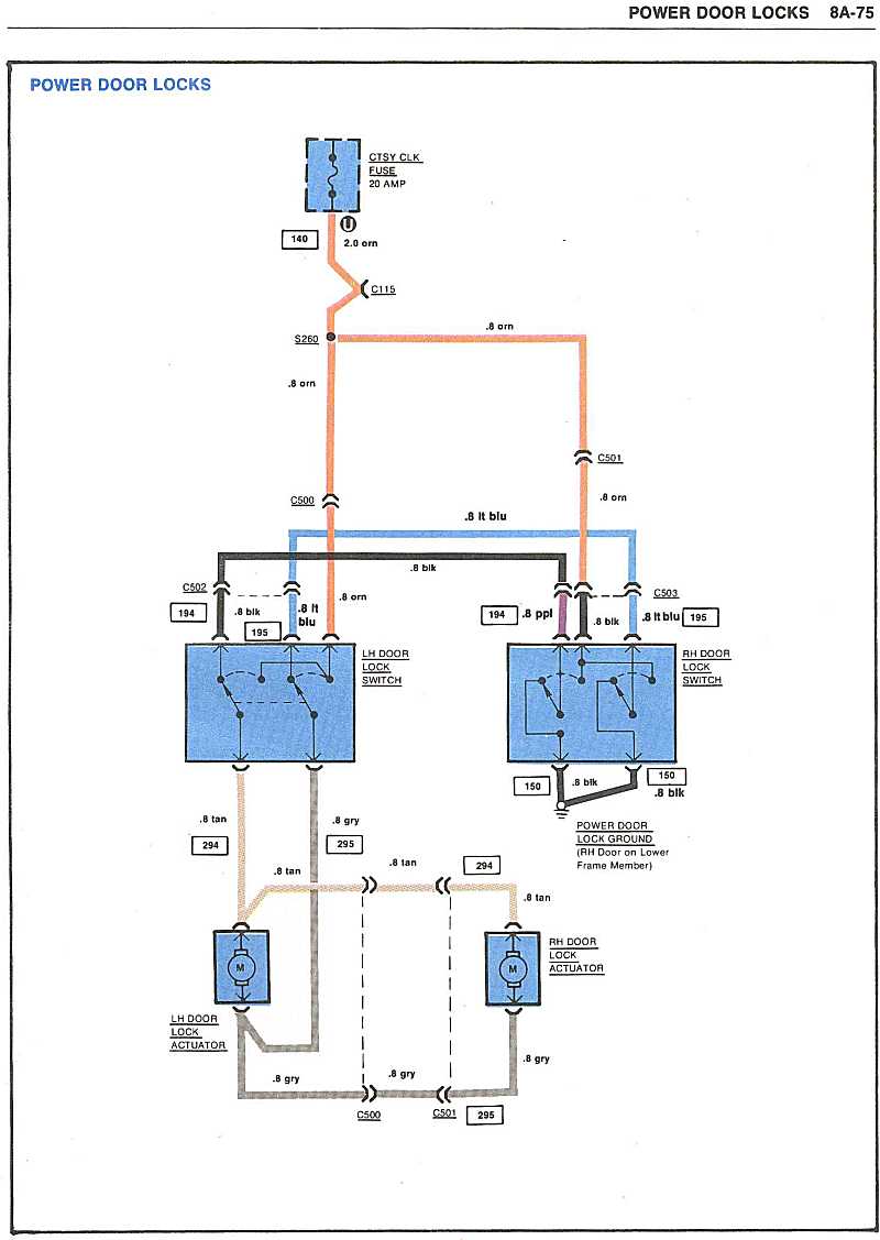
The wiring diagram i posted is from a factory manual. July 21, 2021 · wiring diagram. I posted it just so 75chevyk20 would have access to the original wiring diagram for windows and door locks for comparison purposes.
The relay and wiring are shown in the diagram, above. Correct wire for the power lock is lime w/dark green stripe. Pink/violet power door unlock positive wire location:
Yellow door trigger negative wire location: Here are the new corvette door lock switch pigtails we received from zip corvette parts. 99 wiring diagram power door lock.
Lock the door then push the door actuator all the way down. Power door lock wiring diagram. Attach the rod adapter to the actuators rod and tighten the screw figure 3.
One wire has constant (+) 12v dc at all times. If anyone is interested i can post pics later. Discussion starter · #1 · aug 16, 2005.
Use door trigger (requires relay). Single wire door lock systems require external relays or a relay module and resistors. When overall connections are required see the overall electrical wiring diagram at the end of this manual.
At headlight switch domelight supervision wire: The following common wiring diagrams are available: 11+ power door lock wiring diagram.
The power windows on both side door panels work without any problems. Measure resistance between right door lock switch harness connector terminal no. When you make use of your finger or perhaps the actual circuit with your eyes, it is easy to mistrace the circuit.
I checked fuse and its good and i tried using the drives switch out of my truck in his truck and it still didn't work.

Best Power Door Lock Wiring Diagram Arizona in 2021
Power door locks don’t work — Ricks Free Auto Repair

Help with understanding power door lock diagram Honda
I need the wiring diagram for the power windows, door

Repair Guides Electrical System (1999) Power Door

Repair Guides Body, Lock & Security System (2006

19641968 Power Door Lock Wiring Diagram Ford Mustang Forum

Repair Guides Electrical System (1999) Power Door

Repair Guides Electrical System (1999) Power Door

Repair Guides Electrical System (1999) Power Door

1996 F250 Power Door Locks will not work. Ford Truck
Power Doors & Click Image For Larger Version Name Power
Repair Guides Electrical System (2001) Power Door

Repair Guides Electrical System (2000) Power Door

Power Lock Wiring Diagram Wiring Diagram

Ford F 150 Power Door Lock Wiring Diagram Wiring Forums
Repair Guides Electrical System (1999) Power Door

wiring diagram for aftermarket door locks Car Audio
Wiring Diagrams