
This is slightly different than the remote that goes with the circuit in the sbms0 beginners manual so some very minor changes to the design might be necessary. This is the schematic of the remote.
39 Power Inverter Remote Switch Wiring Diagram Wiring
This then allows your inverter to start and power up.

Power inverter remote switch wiring diagram. Another thing which you will come across a circuit diagram would be lines. I think the enclosed diagram is a basic idea of what you want to do. This is based on the mosfet3205.
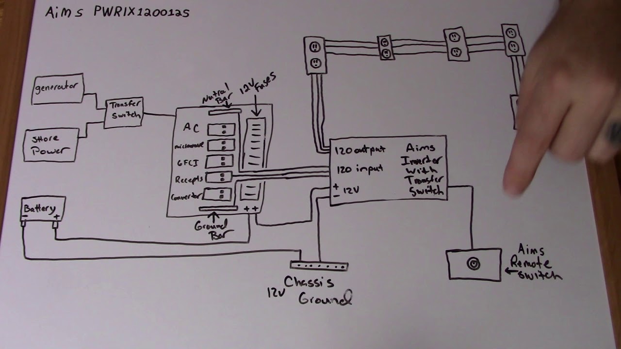
Unfortunately there's no diagram anywhere on how it's wired. Remote switch is sold separately (pn: Rv power converter wiring diagram wiring diagram rv power inverter wiring diagram wiring diagram contains many detailed illustrations that show the link of various products.
Basic schematic for dc to ac inverter 12v 220v circuit pcb diagram the power 100w 2 wind switching transformerless working 240v electronic solar transformer less grid tie supply voltage converter projects on 60w 230v 300watt 24v 1000w pure sine wave simple 48v homemade sinewave circuits 5w 800w. Ups inverter wiring diagrams connection. It’s meant to assist all the typical user in creating a correct program.
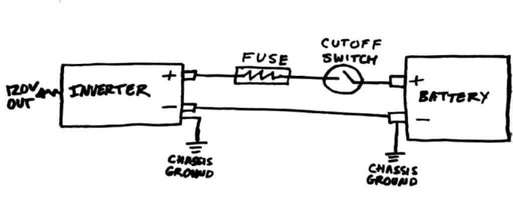
That is the way the giandel inverter remotes work. It’s meant to assist all the typical user in creating a correct program. A fuse box is installed on the positive (red) wire.
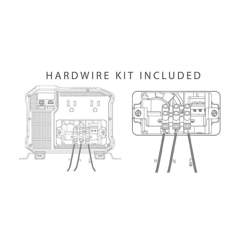
Terminal is used to wire a customer supplied snap style “on/off” switch. Rv inverter install the remote switch. 1000w power inverter circuit electronic schematic diagram.
However, before getting to work, we recommend you the following essential tips for installing an rv inverter: There are just two things that will be found in any power inverter wiring diagram. Led1 is the 'power led' and led 2 is the 'fault led'.
Wiring diagram arrives with a number of easy to stick to wiring diagram instructions. Components of power inverter wiring diagram and some tips. Please careful with this circuit.
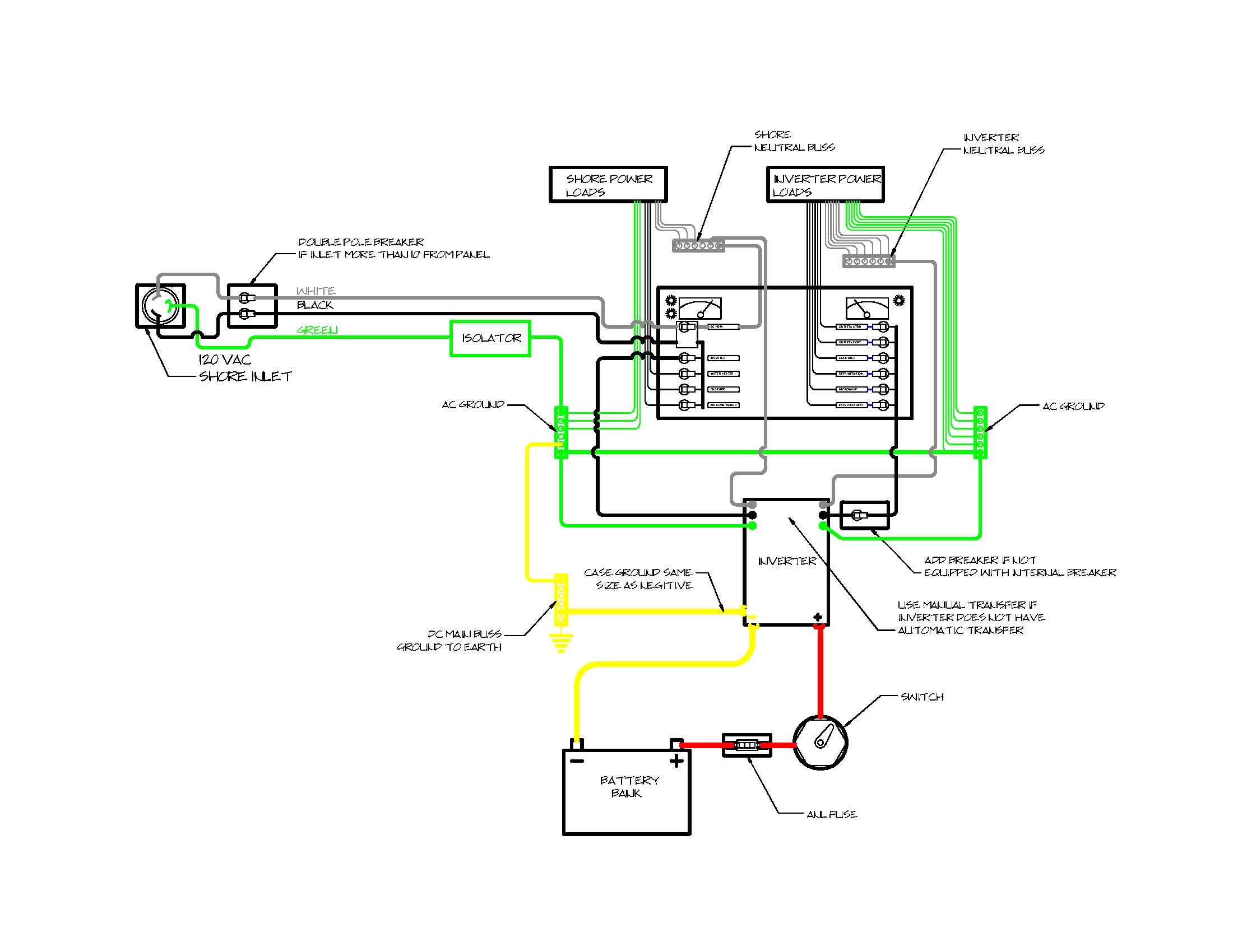
Here is a schematic diagram in pdf and this is a wiring diagram in pdf. Always put a fuse between the battery and the power inverter, so that if a short circuit occurs, the fuse protects the installation. They are usually connected with a standard telephone cable.
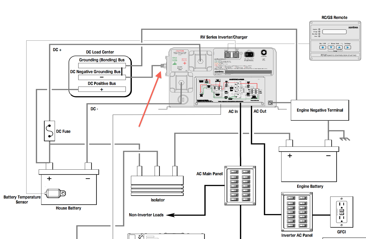
The owner's manual of your inverter will specify the cable size you should use. Remote panel terminal board connections: The shore power connection goes straight to the panel and the inverter has a manual switch to activate it.
It consists of directions and diagrams for various varieties of wiring. I also see no need for any display or control (other than power on/off via bms) on this lump of metal. • remote switch wiring tab:
They do sell wired remote controls for it, like this one so i know it's possible Below you will find the most standard rv inverter wiring diagram. I see no reason to have anything displayed or controlled (except remote on/off via the bms).
Trips to protect the inverter from spikes 11. Remote switches for power inverters can turn your inverter off or on if if is mouted in a hard to reach area. Use 24v dc supply for operation and connect 24v 5a or more than 5a transformer.
Power inverter remote switch wiring diagram. These guidelines will be easy to grasp and implement. Switches the inverter on or off.
These guidelines will be easy to grasp and implement. If we connect high capacity and a greater number of batteries to the battery bank, then the time for which we can take power from the batteries is increased. Cobra cpi a20 power inverter remote control wall plate switch 20 foot wiring high power capacity models compatible.
I even took it apart and couldn't figure out. Remotes can display system information. A circuit is generally composed by many components.
Provides inverter status (see figure 2 on page 7) 9. Used to connect the remote panels (charger and inverter) and the remote “on/off” switch. Wiring diagram arrives with a number of easy to stick to wiring diagram instructions.
In the above diagram, three batteries are connected in parallel to each other and power up the inverter’s dc terminals. For the inverter, i also want simplicity. Cable size also depends on the distance between the inverter and the battery.
This is the circuit diagram of 2000w high power inverter circuit. The first component is emblem that indicate electric component from the circuit. Each part should be set and linked to other parts in particular manner.
A voluntary solar power supply circuit and a transformer may be added within to charge the battery when necessary check diagram.
Xantrex Ags Wiring Diagram
Probing the Mysteries of Power Inverters Part II


Roadtrek Modifications/ Mods, Upgrades, and Gadgets
Understanding Inverter Installations Project Boat Zen
Solar Power Inverter Wiring Diagram Wiring Diagram

[DIAGRAM] Power Inverter Remote Switch Wiring Diagram
Vanagon View topic Verify my Syncro
20 Unique Power Inverter Remote Switch Wiring Diagram

Roadtrek Mods / Modifications, DIYs, Campgrounds, Class B
Simple and clean DC to AC inverter remote switch on mod
Cobra CPI2575 5000w Power Inverter + (2) Cable Kits

Lofrans Control Box Wiring Diagram


39 Power Inverter Remote Switch Wiring Diagram Wiring

Wiring Diagram For Inverter Charger

Remote Operated Switch Detailed Circuit Diagram
39 Power Inverter Remote Switch Wiring Diagram Wiring

Power Inverter Remote Switch Wiring Diagram For Your Needs

Learn Electrician Inverter Wiring Diagram
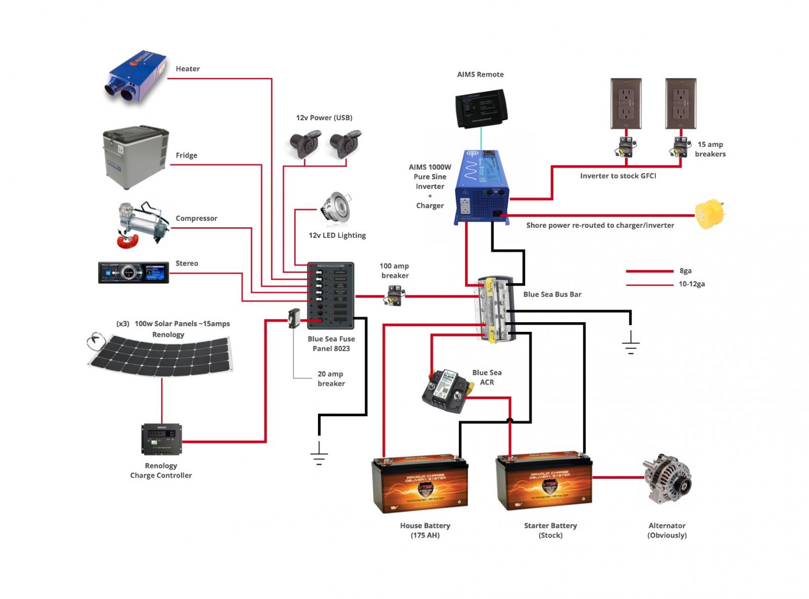
The Best 12V Power Inverters for DIY Campervans and RVs