
All wiring must be done by a licensed electrician. North america phase converters 3.
Three Phase Rotary Converter Wiring Diagram Wiring View
Schematic wiring diagram of three phase distribution board.

3 phase rotary converter wiring diagram. According to earlier the traces in a 3 phase to single phase wiring diagram signifies wires. It shows the elements of the circuit as simplified shapes, and the power and also signal connections between the tools. A wiring diagram is a streamlined standard photographic depiction of an electric circuit.
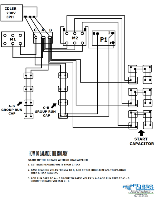
So keep in mind, some things may vary depending on your specific order. Fig 2 electrical wiring diagram of three phase single phase. The idler generator motor attaches to one set of holes in the power distribution block.
June 18, 2020·wiring diagramby hadir. Connect 230 volt single phase power to the t1 and t2 supply terminals (or wires) of the motor that you are using as a converter. The unit used in these videos is an ad series model.
Here are more detailed instructions from this company: Once running, the idler motor 3 phase motor running on single how to use three in rotary converter the home static power convert a into 2 220v two supply 2hp1 5kw 6 amp 200 240v 10kw rs solved 1 has 750w frequency china ie2 110kw ye3 315l1 3hp inverter practical machinist largest pony start 60hp induction drives input hp amps ampere conversion 380v vfd.
440v 3 phase rotary converter help intended for 3 phase converter wiring diagram, image size 900 x 657 px, and to view image details please click the. This guide even contains recommendations for additional provides that you may want to be able to finish your assignments. Fifth, connect your idler generator motor.
Refer to their manual for more detailed info and instructions. Collection of 3 phase rotary converter wiring diagram. A wiring diagram is a streamlined standard photographic depiction of an electric circuit.
Do not use t3 for any single phase loads. The three phase changeover wiring connection and installation is a too simple and easy connection as i showed in the below diagram. Each part ought to be placed and connected with other parts in….
Phoenix phase converter with 3 phase converter wiring diagram by admin through the thousand photographs on the internet about 3 phase converter wiring diagram, we choices the very best collections along with greatest quality only for you, and this images is usually one among graphics collections inside our finest graphics gallery concerning 3 phase. With this kind of an illustrative guide, you’ll be able to troubleshoot, prevent, and full your projects with ease. American rotary phase converter unboxing, setup, and wiring.
In this video i show my setup that i use to take 220vac single phase household power and create both 230vac 3 phase and 460vac 3 phase power using a rotary p. 3 phase rotary converter wiring diagram download. To make a simple rotary phase converter out of a 3 phase motor.
Collection of 3 phase rotary converter wiring diagram. All our pro line 3 phase rotary switch wiring and phase converters include the allen wrenches needed for installation. Ad get rotary phase converter wiring.
Here is a basic wiring diagram from this company and official instruction manual (external link): It shows the elements of the circuit as simplified shapes, and the power and also signal connections between the tools. Fourth option would be a rotary phase converter.
Wiring diagram for loads that american rotary total up to 3 phase idler motor t1 t2 t3 wiring diagram for paralleling multiple phase converters using a transfer switch note all wiring must be done by a licensed phase a matic inc rotary phase converter installation 230v r series rotary converter is 230v single phase in single unit installation diagram. Wiring diagram also gives useful ideas for tasks that might need some added tools. Lw26 20323 rotary changeover switch 500v 3 position three phase panel ing online in kuwait 918502467.
Use the same type of cord to connect the idler motor to the control enclosure. Collection of 3 phase rotary converter wiring diagram. Follow all local, city and national electric codes.
Tool connections can be by hard wired into the converter or by using 3 phase 4 wire Pony start rotary phase converter. Here are some wiring diagrams of rotary phase converters (rpc) that i found on the web.
Thanks to american rotary customer, michael murray, we have a few videos to show you exactly what to expect when you receive an american rotary phase converter. Print the cabling diagram off plus use highlighters to be able to trace the routine. Static phase converter wiring diagram :
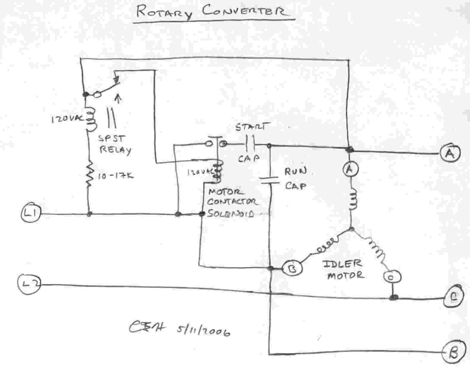
This is a wire sizing diagram (2.2) that they are referring to:

3 Phase Rotary Converter Wiring Diagram For Your Needs

3 Phase Rotary Converter Wiring Diagram Download

Rotary Phase Converter Help and Troubleshooting

3 Phase Rotary Converter Wiring Diagram Free Picture And

Rotary 3 Phase Converter Wiring Diagram downufile

3 Phase Rotary Converter Wiring Diagram Download

Rotary Phase Converter Set Up
Rotary 3 Phase Converter Wiring Diagram ogpowerful

3 Phase Converter Wiring Diagram Fuse Box And Wiring Diagram

Rotary phase converter that only runs when the compressor runs

3 Phase Rotary Converter Wiring Diagram Download
3Phase Converters
Three Phase Rotary Converter Wiring Diagram Wiring View

3 Phase Converter Wiring Diagram Fuse Box And Wiring Diagram
Rotary 3 Phase Converter Wiring Diagram heretup

Three Phase Converter Wiring Diagram Also Three Phase

Rotary 3 Phase Converter Wiring Diagram ogpowerful
Electrical Panel Wiring 3 Phase Professional 3 Phase


3 Phase Rotary Converter Wiring Diagram Download