On trustpilot, spireon scores a very impressive 4.6/5 from nearly 100 reviews. * see wiring diagram for details 4.
Extracting a dealershipinstalled nightmare from my dream
Capterra reviews are similarly impressive and are far more focused on the fleetlocate product.
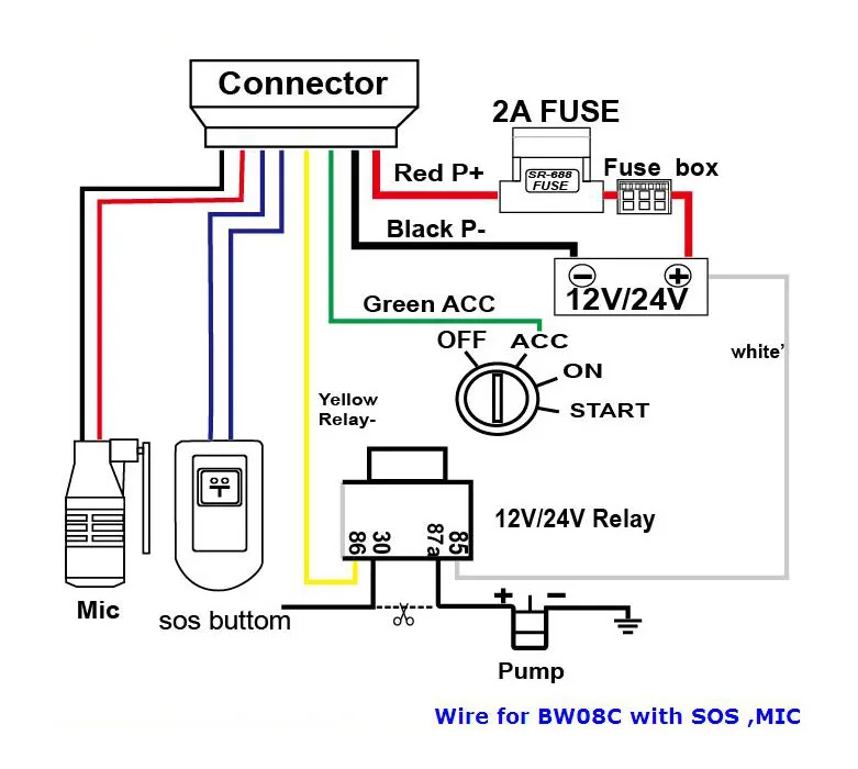
Spireon gps wiring diagram. Car gps wiring diagram wiring schematic diagram. Ground was a door hinge bolt. One wire connected to the red wire on the ignition to provide power to the device (there is a battery in the device itself) one wire to vehicle ground.
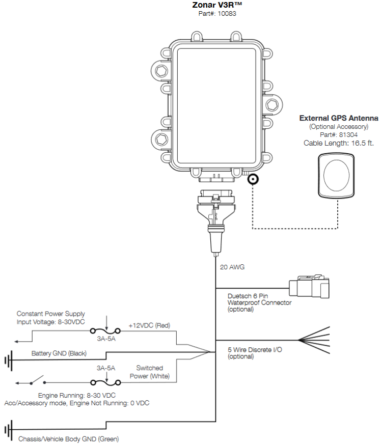
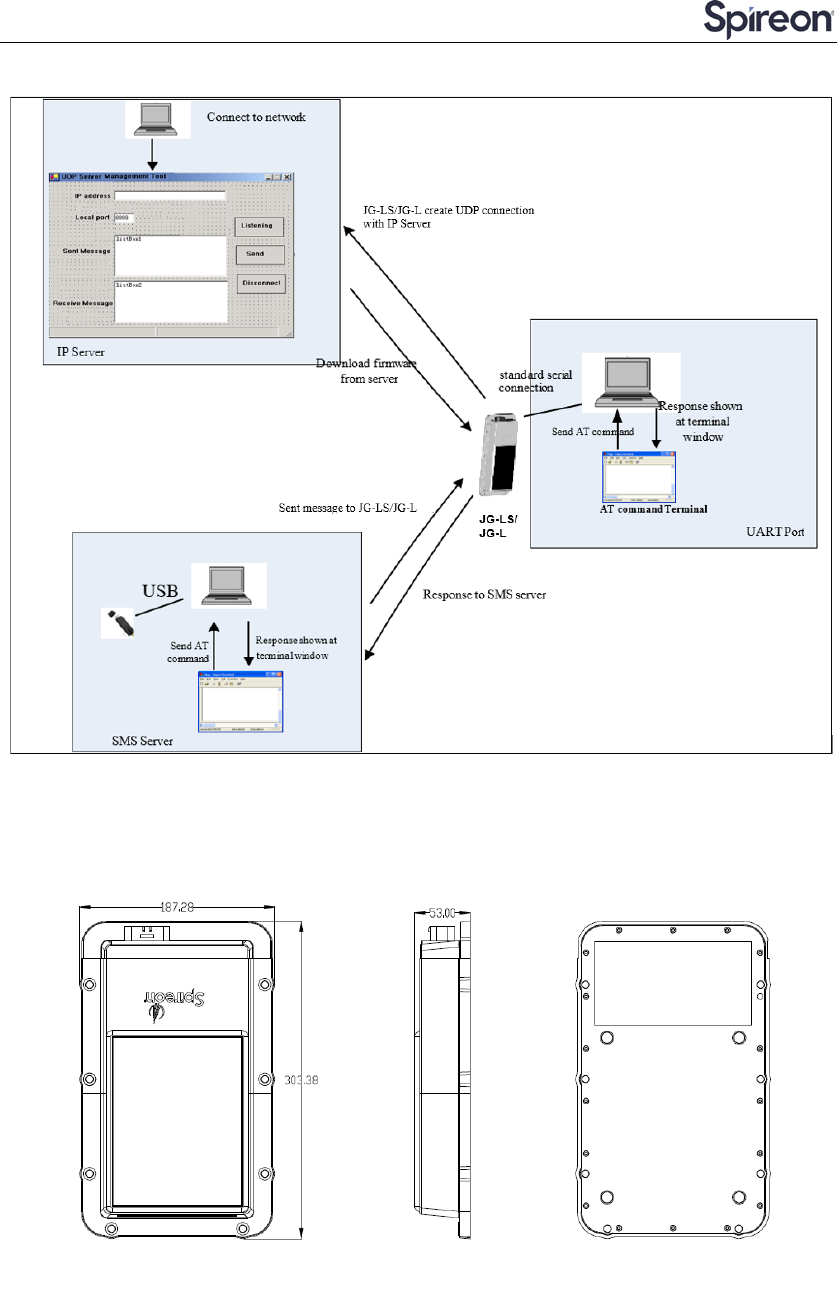
Proper gps device installation is vital to the success of all spireon services. An fcc id is the product id assigned by the fcc to identify wireless products in the market. Installation fl18™, vp2500™, vp2502™ if you have any questions regarding your device, please call:
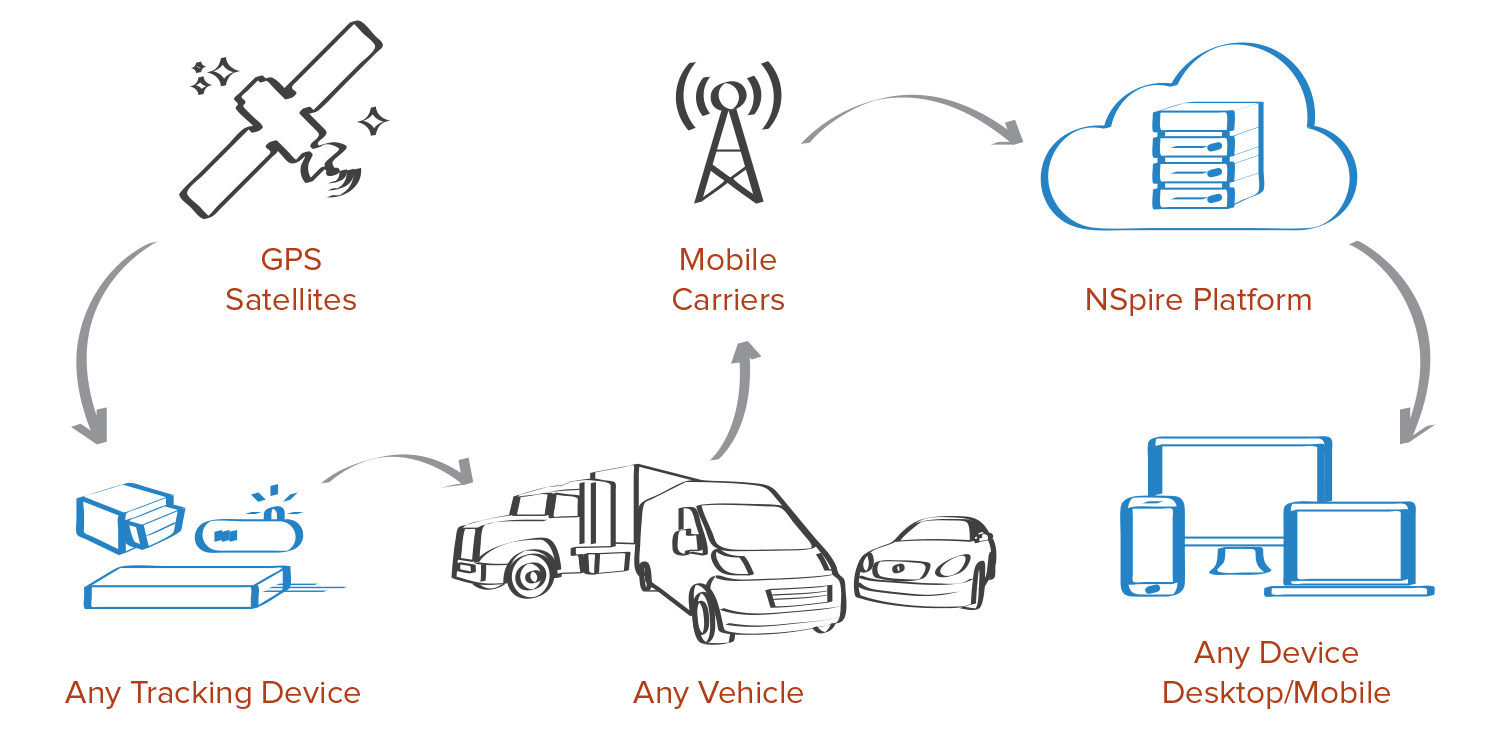
Pdf file type extension : The remaining characters of the fcc id, jks3, are often associated with the product model. This device communicates its location at regular intervals, allowing the owner of the car to be notified via a smartphone application of the vehicle’s current location, or whenever specific events occur such as geofence entry or exit, low battery, or speed limit.
Connect the wires according to the following table: Gps theft recovery systems rely on a connected device installed in the vehicle. And subscribe to our youtube channel for more videos coming soon!
That's a pretty common way to locate them. Doorbell wiring diagram best of goldstar gps circuit fair gold star in, how to wire a vehicle gps tracking device for power and ground within goldstar gps wiring. Is marked by a sticker on the vtu, showing “gps this side up”.
Predictive location data and history. I cut my hands up something awful (it was velcroed in place) but got it out. Get the data, video and intelligence you need to maximize route efficiency, increase driver safety, manage maintenance, and ensure compliance.
(“spireon”) gps product you just purchased is warranted to be free from defects in materials and workmanship. Your gps product utilizes cellular telephone and global positioning satellite communication. Stipulation event tracking to collect work and home addresses within the first 14 days of installation.
I stuck my head under the steering column and saw a red wire wrapped around the column, leading to a wiring harness and clearly out of place. One wire was the gsm antenna. Connect the red wire in the device harness to +12v power connect the black wire in the device harness to chassis ground.
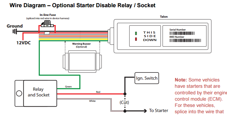
This is the most commonly used application for disabling the starter. The two relay wires that wired into the black wire to the ignition. 2017:08:01 18:31:30+08:00 tagged pdf :
Do not plug the power cable into the vtu at this time!! Inspirational goldstar gps wiring diagram free image circuit maker at, goldstar gps wiring diagram chunyan me new, goldstar gps wiring diagram spireon and. Spireon gps vehicle tracking for auto fleet trailer asset.
Connect white ignition sense wire to the vehicle’s ignition source. 2017:08:01 18:31:25+08:00 modify date : Fleet cost savings resources fleetlocate by spireon.
Simply put, if a technician does not install the device correctly, your spireon service won’t work. The fcc chooses 3 or 5 character grantee codes to identify the business that created the product. Take control your entire fleet with fleetlocate.
It was located next to the eye. Within the case are two antennas for both gps data and gsm/gprs communication. The gps box itself was stuffed up on top of the steering column.
After removing a few trim panels, i was able to remove power and ground from the. Ford, to another relay), when the alarm is armed and the ignition is turned on. Goldstar gps wiring diagram 2015 ford f 150 wiring diagram hdmi.
Goldstar gps wiring diagram awesome new toyota tundra sr5 in langhorne pa team toyota of langhorne of goldstar gps wiring diagram in goldstar gps. It's hard to make the wiring look factory without some pretty serious time and effort, which isn't tricking down to the installer. Eea3 spireon gps wiring diagram wiring resources.
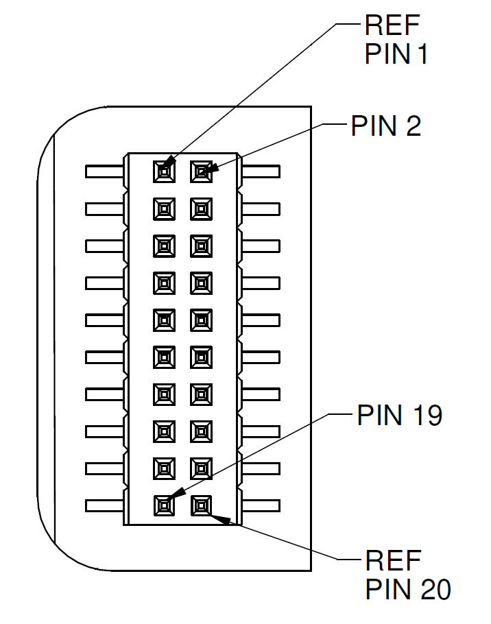
Recently, i had time to poke around my truck and locate the spireon gps tracker that had been installed and never removed. The basic starter kill relay diagram shown below, breaks continuity of the wire from the ignition switch to the starter motor (or in some cases i.e.; From the power harness’ white wire · remove the nut on the terminal for pin #6 in the j560 (tail/license plate lamps) and connect the ring terminal from the power harness’ brown wire · remove the nut on the terminal for pin #7 in the j560 (aux/abs) and connect the ring terminal from the power harness’ blue wire power harness diagram:
Doorbell wiring diagram new goldstar gps. Rennan zhao create date : For example, the grantee code for fcc id:
Retrieve password © 2022 spireon, inc. (“spireon”) gps product you just purchased is warranted to be free from defects in materials and.

Spireon Gp Wiring Diagram Complete Wiring Schemas
Gps Wiring Diagram Wiring Diagram Dash

Spireon Gp Wiring Diagram Complete Wiring Schemas
Spireon Gp Wiring Diagram Complete Wiring Schemas
Spireon Gp Wiring Diagram Complete Wiring Schemas

Spireon Gp Wiring Diagram Complete Wiring Schemas
Wiring Diagram For Gps Tracker schematic and wiring diagram

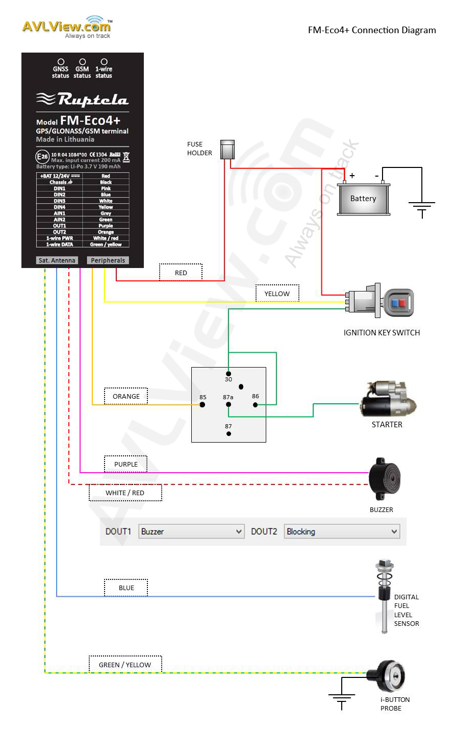
How to install Ruptela GPS tracking device?
Spireon Gp Wiring Diagram Complete Wiring Schemas

Gold Star Gps Wiring Diagram Wiring Diagram

Spireon Gp Wiring Diagram Complete Wiring Schemas

Goldstar Gps Wiring Diagram Free Wiring Diagram

Spireon Gp Wiring Diagram Complete Wiring Schemas
Spireon Gp Wiring Diagram Complete Wiring Schemas
![]()
Jual GPS Tracker GT02D GT02 Free Server Web Tracking
Spireon Gp Wiring Diagram Complete Wiring Schemas
![]()
Spireon Gp Wiring Diagram Complete Wiring Schemas
30 Gold Star Gps Wiring Diagram Wiring Diagram Database


Spireon Gp Wiring Diagram Complete Wiring Schemas