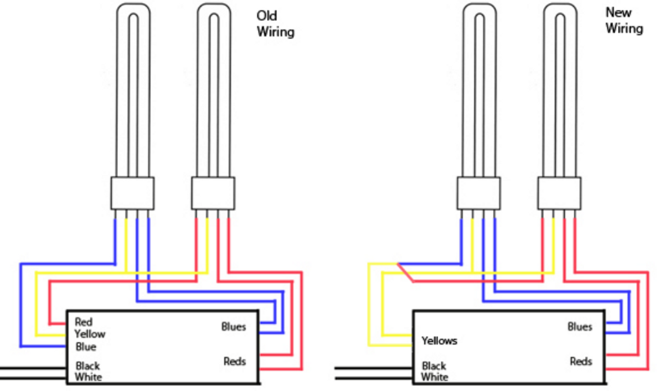
Yellow terminals are not used. Each part ought to be set and linked to other parts in particular manner.
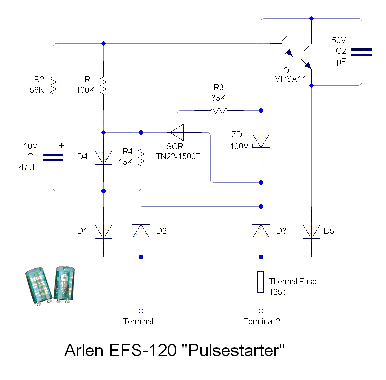
Electronic Ballast Wiring Diagram LIZAMOI
Most newer cfl ballasts operate on 120v to 277v.

Compact fluorescent ballast wiring diagram. May be used with other ballasts. Instructions and wiring diagrams on each ballast label help assure a correct installation the first time. Rapid start ballast wiring 4 lamps electrical 101.
Little differency is in powering tubes before d6 diode and wiring of start capacitors c10 a c11 about tubes. • each ecosystem digital link supports up to 64 digital Wiring diagram of single tube light installation with electromagnetic ballast tube light light switch wiring lighting diagram.
For use with other line voltages, remove wire nut splicing the black lead from the supply lead and the 277v lead from the ballast. Each component ought to be placed and connected with different parts in particular manner. Rapid start ballast lampholder wiring 2 and 4 lamps electrical 101.
Compact fluorescent lamp circuits andor low power electronic lighting ballasts. The ballast for a rapid start fixture has in. For schematics thanks to mard.
It includes guidelines and diagrams for various kinds of wiring methods as well as other items like lights, home windows, and so forth. It starts with precision manufacturing. Emergency ballast and ac ballast must be fed from the same branch circuit 1.b) flex conduit wiring diagram:
Total performance system™ warranty here are the facts behind the promise. Input power total power input to the ballast which includes lamp watts and ballast losses. 1 electronic ballast block diagram.
Fluorescent tubes require a ballast to operate. For 4 pin compact fluorescent lamps dial the four digit extension of the factor. Wiring diagrams and descriptions to help you understand fluorescent ballasts including series and parallel ballasts volt electronic ballast for 4 ft.
How to read a compact fluorescent ballast table ballast factor ratio of the lamp’s lumen output on the specified ballast to the lamp’s lumen output when operated by a reference ballast. Fluorescent lamp working principle and wiring diagram learn electrician. Lamp eurolite 23w has a classic wiring diagram.
4 pin cfl wiring diagram. 2.a) flex conduit wiring diagram: August 7, 2021 on 4 pin cfl wiring diagram.
It is extremely simple to draw a wiring diagram; You just require to have a good comprehension on different types of wiring and their purposes. A wiring diagram is a streamlined standard pictorial representation of an electric circuit.
Instant start ballasts can only be wired in parallel according to the diagram on the ballast. In commercial buildings cfls are commonly used in recessed lighting and use a separate ballast to power the lamps (bulbs). 40 watt electronic ballast circuit homemade projects.
Fluorescent lamp circuit diagram with electronic ballast wiring diagram and schematics wiring diagram and schematics this place is a growing library of the schematics, wiring diagrams and technical photos Before installation make certain supply and ballast voltages are compatible. Consult the factory for other wiring diagrams.
Wiring diagram consists of numerous comprehensive illustrations that show the link of assorted things. In commercial buildings cfls are commonly used in recessed lighting and use a separate ballast to power the lamps (bulbs). Cat 5a wiring diagram ethernet wiring rj45 electrical circuit diagram.
Cfl ballast with 2 lamp wiring diagram. Open fixture and remove the bulb and ballast casing. Compact fluorescent lamp (cfl) english:
Compact fluorescent ballast wiring diagram. A wiring diagram is a streamlined standard pictorial representation of an electric circuit. Red wires connect to one side of the lamp, blue wires connect to the other.
T8 fluorescent ballast wiring diagram wiring diagrams thumbs ballast wiring diagram t8. Cfl ballast with 2 lamp wiring diagram. Wiring diagram references the wiring diagram to use.
Fluorescent emergency ballast wiring diagram a novice s overview to circuit diagrams. Red wires connect to one side of one lamp, blue wires connect to one side of the other. Collection of electronic ballast wiring diagram.
Otherwise, the arrangement will not work as it ought to be. Wiring diagram number watts lamp data size 1 160 10 0 96 cfq13w g24q 13w cfl quad tube lamp. Ecosystem compact fluorescent ballasts digital dimming ballasts 369339h 6 03.06.18 ecosystem bus wiring diagrams ecosystem digital link overview • the ecosystem digital link wiring (e1 and e2) connects the digital ballasts and drivers together to form a lighting control system.
Fluorescent ballast wiring diagram 8 foot fluorescent ballast wiring diagram advance fluorescent ballast wiring diagram compact fluorescent ballast wiring diagram. Typical compact flash lamp ballast circuit 10 15 fluorescent scientific diagram. Yellow terminals wires connect to the remaining pins.
Cfl ballast with 2 lamp wiring diagram. In commercial buildings cfls are commonly used in recessed lighting and use a separate ballast to power the lamps bulbs. Electronic ballast sinecan 5 for two fluorescent tubes has identical circuit like most of compact fluorescent lamps.
Changing the wiring on a fluorescent light fixture from rapid start to instant start, involves changing the wiring from series to parallel. We work to assure you the
fluorescent lamp circuit diagram with electronic ballast

Ballast Wiring Diagram Wiring Diagram
fluorescent lamp circuit diagram with electronic ballast
fluorescent lamp circuit diagram with electronic ballast
fluorescent lamp circuit diagram with electronic ballast
Electrical Circuit Diagram Fluorescent Lamp Wiring
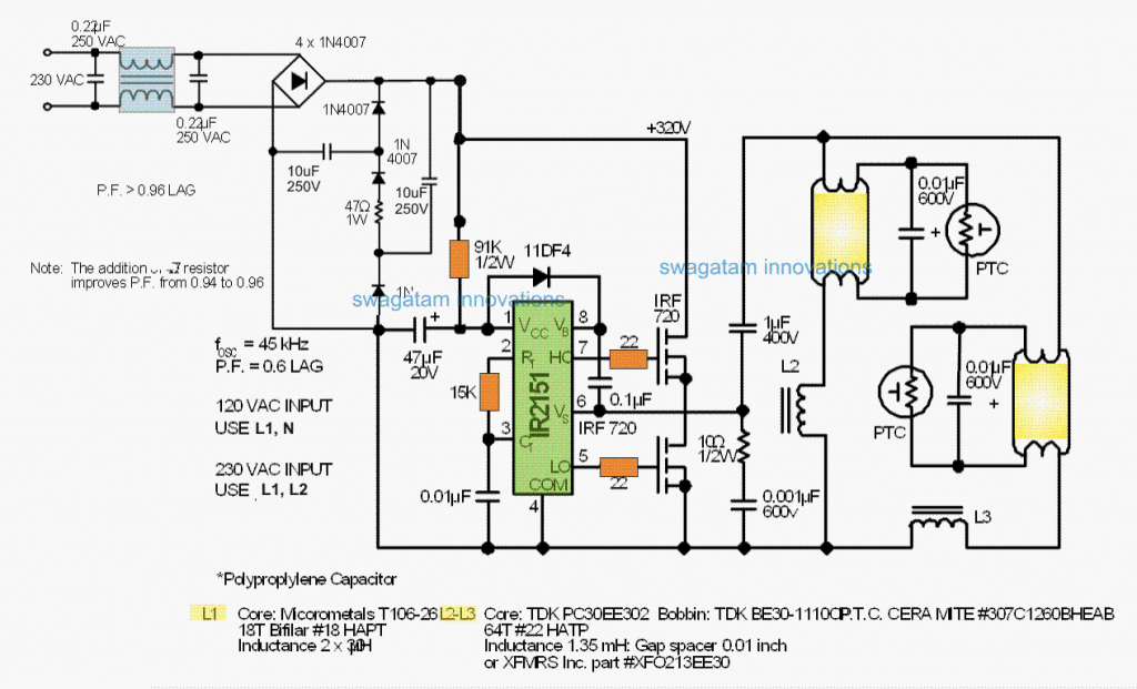
Pdf Electronic Ballast Wiring Diagram Wiring Diagram
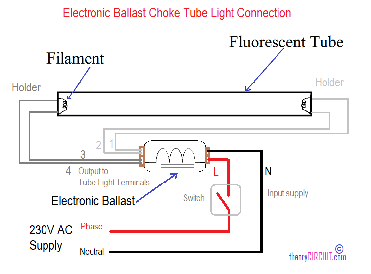
double tube light connection with choke and starter

PSM226CQMVDWCEST Robertson Compact Fluorescent Ballast

T8 Ballast Wiring Diagram Robertson Complete Wiring Schemas

Electrical Circuit Diagram Fluorescent Lamp Wiring
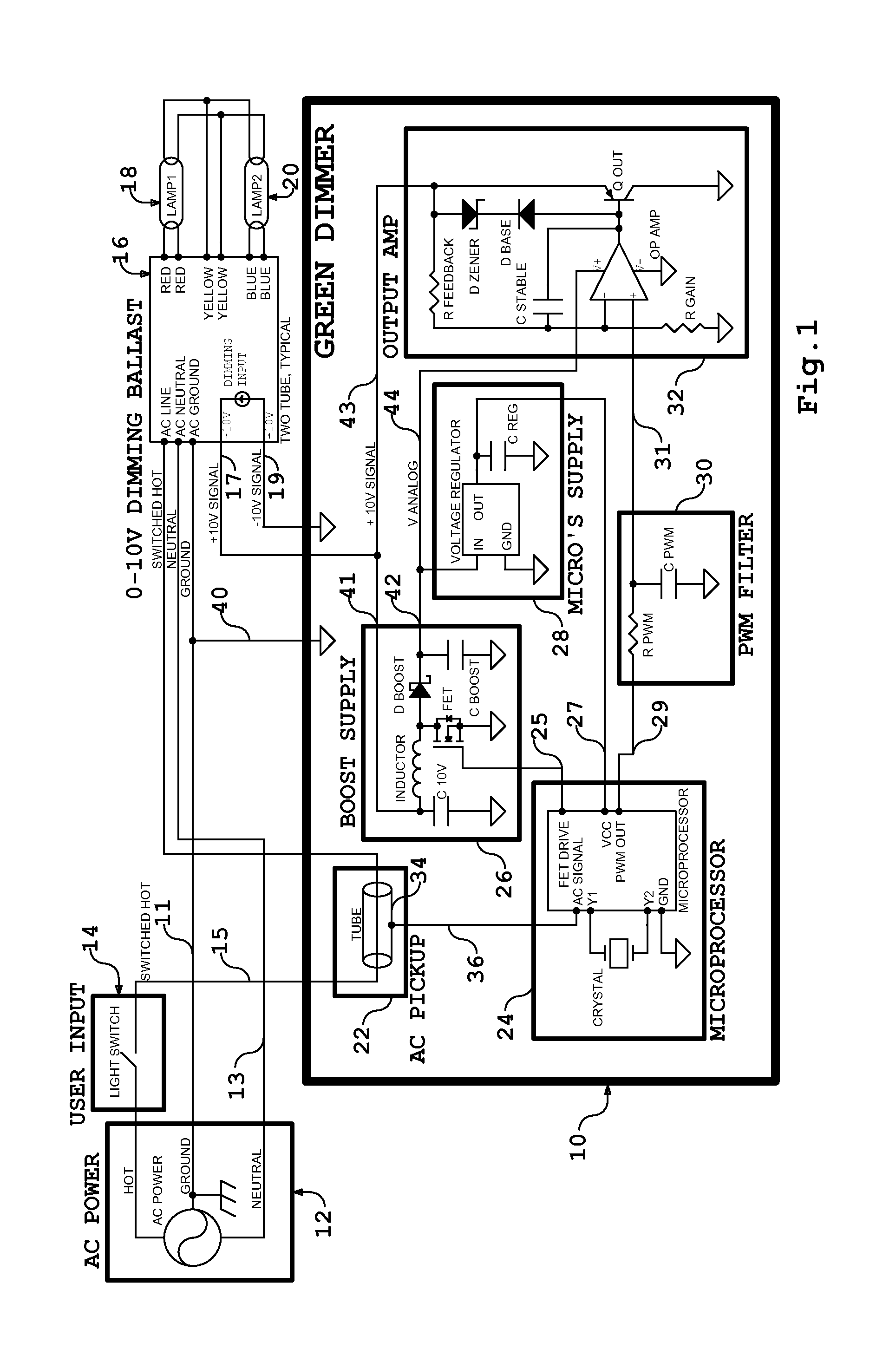
Advance Mark 7 Dimming Ballast Wiring Diagram

Ballast Wiring Diagram Wiring Diagram

Compact Fluorescent Lamp (CFL) Electronics repair guide

Fluorescent Lamp Wiring Diagram Pdf Wiring Diagram Schemas
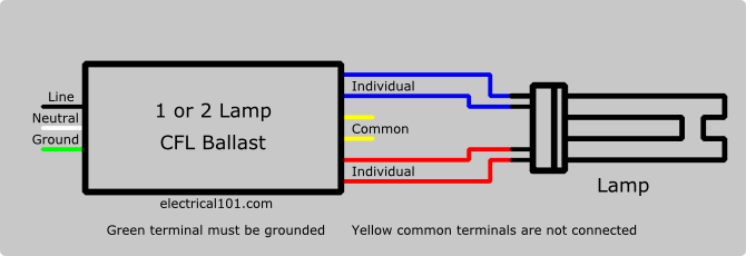
CFL Ballast Wiring Electrical 101
