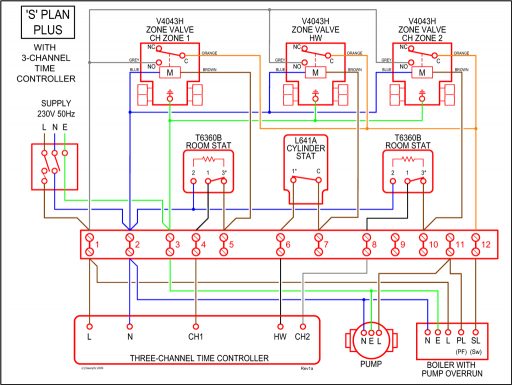
The d4120 and d4p120 leds indicate the status of power, maintenance, trouble, and local alarm conditions. March 23 2018 by headcontrolsystem.
System Sensor D4120 Wiring Diagram
Smoke detectors designed for use in air duct systems are used to sense the presence of smoke in the duct.
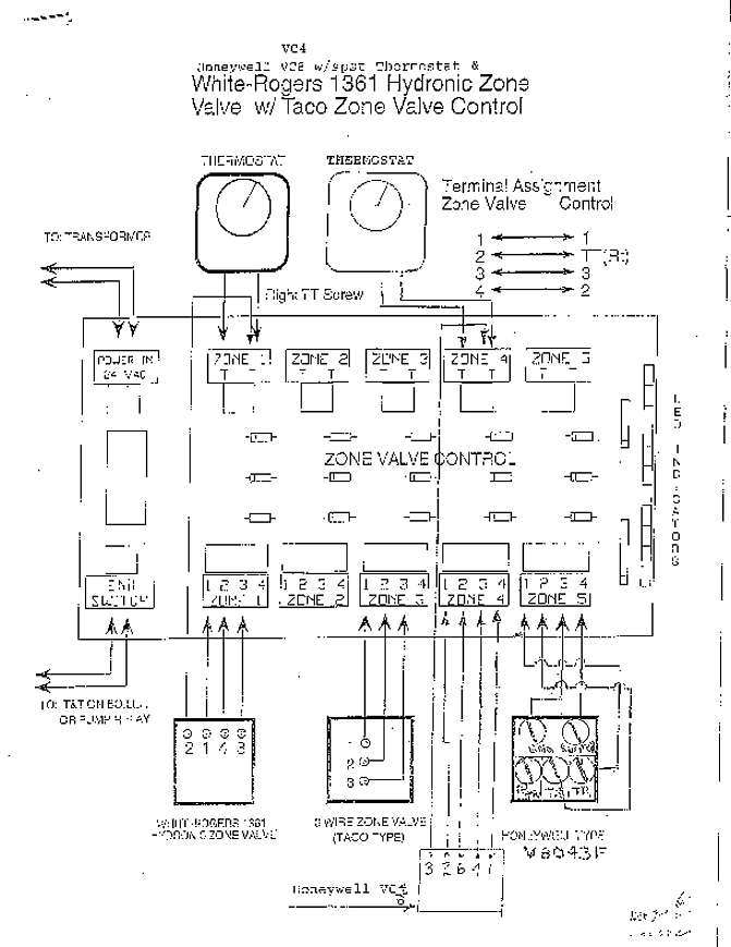
System sensor d4120 wiring diagram. Not all screw terminals in the dsd compartment are shown, for clarity. The detector housing shall be ul listed per ul 268a or ulc listed specifically for use in air handling systems. Verify the duct air velocity drill a small hole at the point where the duct smoke detector is being installed.
067 to 246 obscurationft reset time. Diagram circuit of addressableire alarm system control panel wikipedia readingrat net throughout. This manual is available online at www.systemsensor.com.
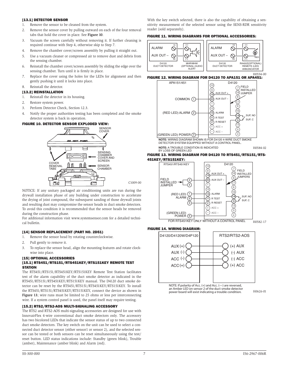
System sensor d4120 wiring diagram user guide • read online or download pdf • system sensor d, d duct smoke detector installation and maintenance instructions. This detection method, when combined 2.these wiring diagrams apply to model d4120 duct smoke detector (made by system sensor) with either photoelectric detector head.
Duct smoke detector wiring diagrams weatherproof ionisation firex 2650 761 photoelectric 115 230 series d4120 dn 60267 notifier help with 74 3440 tc806d1049 cdn tc806d1056 d4s sensor 器duct ductsd addressable detectors jmac supply honeywell d355pl installation and. Smoke detectors designed for use in air duct systems are used to sense the presence of smoke in the duct. You are able to usually rely on wiring diagram as an essential reference that will.
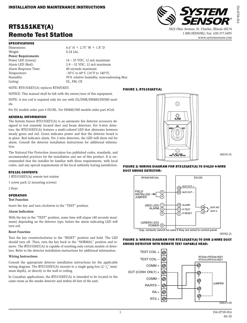
Rts151 remote test station installation and maintenance instructions 3825 ohio avenue, st. The innovairflex housing provides ample wiring space, a the air duct smoke detector shall be a system sensor innovairflex™ d photoelectric duct. Smoke introduced into an air duct system will be distributed throughout the entire building.
This detection method, when combined System sensor d4120 wiring and rts how and why and testing System sensor smoke detector wiring.
These wiring diagrams apply to model d4120 duct smoke detector (made by system sensor) with either photoelectric detector head. Diagram wiring diagram for duct smoke detectors full version hd quality smoke detectors resdientdata aube siae fr. It reveals the elements of the circuit as streamlined shapes and also the power and also signal connections between the devices.
The flexible housing of the duct smoke detector fits both square and rectangular footprints. The air duct smoke detector shall be a system sensor innovairflex™ d4120(a) photoelectric duct smoke detector. Smoke introduced into an air duct system will be distributed throughout the entire building.
Smoke detectors designed for use in air duct systems are used to sense the presence of smoke in the duct. System sensor convention 4 wire duct smoke detector d4120 wiring instructions youtube. Nfpa standards 72 and 90a should also be referenced for detailed information.
System sensor duct detector wiring diagram. D4120 duct smoke detector d4s sensor component d4p120 power board component pdf free download duane weigle senin 06 desember 2021 learning to read and use wiring diagrams makes any of these repairs safer endeavors. Read system sensor’s applications guide for duct smoke detectors (hvag53), which provides information on detector spacing, placement, zoning, wiring, and special applications.
Wiring diagrams are designed to be easy to comprehend and easy to build. The d4120 and d4p120 incorporate a cover tamper feature
System Sensor D4120 Wiring Diagram Using A Manometer To
System Sensor D4120, D4P120, and D4S User Manual Page 5 / 8
System Sensor D4120 Wiring Diagram / System Sensor D4120
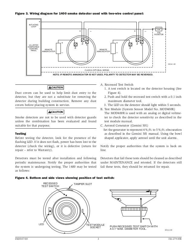
System Sensor D4120 Wiring Diagram
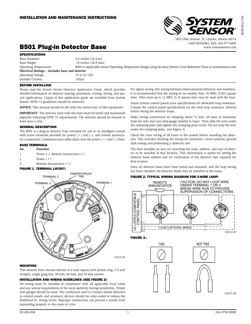
System Sensor 2351e Smoke Detector Wiring Diagram Wiring
System Sensor D4120 Wiring Diagram / System Sensor D4120

System Sensor D4120 Wiring Diagram
System Sensor D4120, D4P120, and D4S User Manual Page 7 / 8

System Sensor D4120 to RTS. Wiring and testing procedure

System Sensor D4120 Wiring Diagram

System Sensor D4120 Wiring Diagram Ff 2773 System Sensor
System Sensor D4120 Wiring Diagram / System Sensor D4120

System Sensor D4120 Wiring Diagram
System Sensor D4120 Wiring Diagram Using A Manometer To
System Sensor D4120 Wiring Diagram Wiring Diagram

System Sensor D4120 Wiring Diagram

System Sensor D4120 Wiring Diagram / System Sensor D4120

System Sensor D4120 Wiring Diagram


